Cooling System
General
Cooling system
Volvo Penta only uses liquid-cooled engines. The cooling system comprises a cooling water system and a cooling air system. The objective of the system is to lead heat from the engine to the surrounding atmosphere. Around 40 % of fuel energy is used to perform mechanical work, while the rest is lost as heat to the coolant and through the exhaust. The heat that is transferred to the coolant is 20-30 % of the fuel energy, and it must be carried away by the cooling system. The water pump forces coolant through the engine cooling ducts. Hot coolant enters the radiator, passes through pipes and is cooled by cooling air from the fan. In order to increase power and reduce exhaust emissions, a charge air cooler may be used. Volvo Penta uses two different types of charge air cooler. TWD engines have a water-to-air charge air cooler in which hot charge air is cooled by engine coolant. TAD engines use air-to-air charge air coolers in which charge air is cooled by cooling air from the fan. This type of charge air cooler is installed separately behind (or in front of) the regular radiator.
The cooling system must be dimensioned so that engine overheating is avoided during all ambient and operational conditions. It is therefore important to know the maximum air temperature and the environmental conditions where the engine will be used. Cooling requirements differ from engine to engine, and heat transfer to coolant is specified in the Sales
Support Tool, Partner Network for each engine. Additional to the heat transferred to the coolant from the engine, heat transfer from extra equipment, e.g. via the torque converter oil cooler, must also be taken into account when a cooling system is dimensioned. Cooling is also affected by obstacles to airflow and temperature increases above air-cooled accessories such as air conditioning condensers or air-cooled oil coolers. Air can also be heated by the engine and generator (generator set) before it passes through the radiator. In order for cooling to be as efficient as possible, it is important to minimize cooling air obstacles and prevent air recirculation by designing cooling air ducts and grilles correctly. Regarding the smaller VE series engines for which Volvo Penta does not provide a complete cooling assembly, all relevant data for the design of a correct cooling system is available under “Cooling system” and “Charge air cooling system” in the Sales Support Tool.
Fan
Function
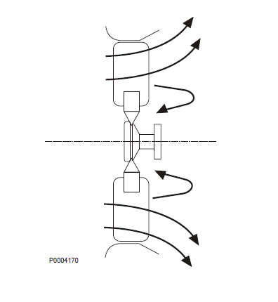
The function of the fan is to provide a cooling air flow. The fan creates a pressure increase that provides an air flow through the system components. Increased cooling air speed through the radiator core results in increased heat transfer from the fins to air. The air flow created by the fan depends largely on the pressure drop from components in the system. The fan is of axial flow type, but the air flow is not entirely axial. With an increase in installation pressure drop the air flow becomes more radial. The fan is usually belt driven, but on mobile applications certain engines also have crankshaft-mounted fans as an option. A crankshaft-mounted fan is exposed to higher stresses than a belt-driven fan. There are two main types of axial fans: fixed fans and temperature-controlled fans. The fan is an installation safety item and Volvo Penta fans are thoroughly tested before they are approved. Volvo Penta therefore recommends that only genuine Volvo Penta fans be used.
Fixed fans
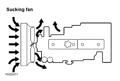
Fixed fans are used wherever large, continual cooling air flows are required. They are also used in installations where noise levels and fan power consumption are less important. Volvo Penta provides two different fan types: plastic fans and fans with aluminum blades that are riveted to twin steel hubs. Crankshaft-mounted fans must have rubber hubs to reduce vibrations from the crankshaft. There are two types of fan depending on the direction of airflow:
• Sucking fan (draws air in)
• Pusher fan
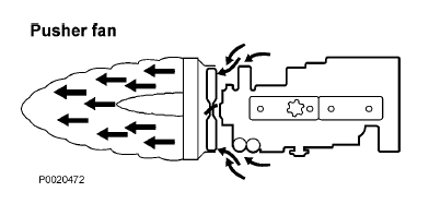
A sucking fan pulls cooling air through the radiator while a pusher fan blow air through the radiator. The following factors must be considered when determining the most suitable air flow direction for the installation:
1 The same fan diagram applies to two similar fans where only the air flow direction differs.
However, both pressure drop and cooling capacity are changed if air flow direction is changed on a given installation.
2 Wherever possible the air flow direction must be such that the air temperature at the radiator inlet is as low as possible (close to ambient temperature). This means that a sucking fan usually
provides the best cooling capacity. In the case of a pusher fan, air is heated by the engine before it passes through the radiator.
3 It is easier to achieve an even distribution of air flow over the radiator surface if a sucking fan is used instead of a pusher.
4 A pusher fan is usually required on gen set applications to ensure sufficient generator cooling.
5 On mobile applications with relatively high forward speeds air flow direction must be selected to draw benefit from the slipstream.
Temperature controlled fans
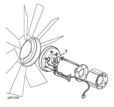
On temperature controlled fans, fan speed is controlled by engine temperature. The fan only runs when it is needed, which means that it uses less power and is quieter than a fixed fan. Silicone oil is used to transfer rotation to the fan via a rotating disc in a visco fan coupling (1), controlled electronically. Fan deployment is controlled by the coolant and charge air temperatures. The advantage with an electronically controlled fan is that the engine only need engage the fan when it is required and this saves fuel with varying loads. Note that the visco coupling must never be laid on its side
(e.g. when removing fan components), as the silicone oil will leak out. There is always a certain amount of slippage when the fan is engaged. The coupling must be designed for a given drive speed in order to function correctly. Volvo Penta uses couplings of viscous type for temperature controlled fans.
Fan capacity
Fan plot (A)
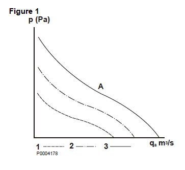
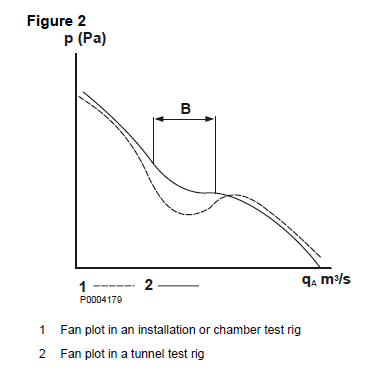
The fan creates the greatest rise in pressure when it is working against a high back pressure, when it provides little air flow. The pressure increase across the fan reduces with higher air flows. The fan plot in figure 1 shows increases in static pressure in comparison to different air flow speeds (1, 2, and 3 in figure 1). There is a section on the fan plots with a epression called the stop zone (B). The fan is somewhat unstable in this zone and in realistic conditions the fan would work to the right of this zone; see figure 2. To the left of the stop zone the major part of the air flow from the fan is radial. Fan capacity plots issued by manufacturers usually refer to tests carried out in a tunnel test rig. The fan does not behave in the same way on an engine installation, but more like in a chamber test rig. The fan plots derived from the two different test methods are shown in the adjacent graph. The stop zone on engine installations is not as distinct and the fan plot is a little further to the right of the stop zone.
System plot (C)
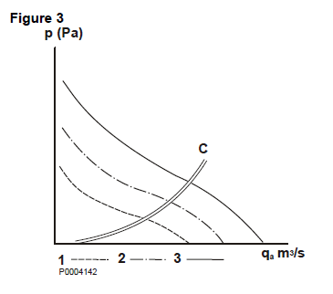
Every air cooling installation has a given pressure drop for a given air flow. There is a point where the pressure increase across the fan coincides with the pressure drop across the installation at a given fan speed. This point in the fan graph is the working point at the actual fan speed. If the working points for different fan speeds are joined by a line the installation system plot is derived. See figure 3.
Air flow and pressure increases that a fan is able to create in a given installation are always determined by the fan plot and system plot intersection. The system plot can be expressed by the formula:
p = k x qA
2
p = increase in static pressure (Pa)
k = constant, dependent on installation
qA = air flow (m3/s)
The value k must be as low as possible for the installation, and is affected by all the components in the air cooling system. An installation with a small radiator surface area often has a high k value. The total cooling air pressure drop is around 2-3 times greater than the pressure drop across the radiator on uncovered generator set engine installations of types TD or TWD.
For More Volvo Engine workshop information, please visit
Sound Absorption of Volvo Diesel Engine
Volvo Engine Mountings for Mobile Installation
Copyright © Guangxi Dingbo Generator Set Manufacturing Co., Ltd. All Rights Reserved | Sitemap
Update cookies preferences