Engine Speed Regulation, Mechanical / Electronical Regulator
The governor controls engine speed and any generator frequencies. The extent to which a governor regulator controls engine speed depends on governor specifications.
For a given position of the control lever there is a power/engine speed relationship (at stable load intervals) called
"governor control" or "speed reducing".
This relationship indicates the change in engine speed expressed as a percentage of rated engine speed.
engine speed without load (NO) – engine speed at full load (NR)
Engine speed reduction % = ––––––––––––––––––––––––––––––––––––––––––––––––– x 100
engine speed at full load (NR)
Example: If the rated engine speed is 1,800 rpm at full load and 1,800 rpm without load.
1,880 - 1,800
Engine speed reduction % = ––––––––––– x 100 = 4.5 %
1,800
Synchronous engine speed is defined as operations between no load and full load with a 0 % reduction.
Control variations may influence governor stability. Attempts to minimize the control of mechanical governors by more than their design permits may mean that such control becomes unstable.
Stability is the governor's ability to establish a pre-determined engine speed and stabilize it quickly.
All governors require a given time period to act and a governor with poor stability will continue to oscillate above or below the rpm required or take a long time to stop oscillating.
Load acceptance
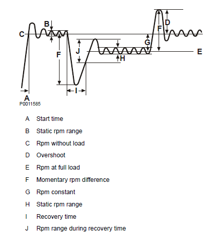
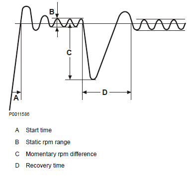
Generator set engines have sufficient capacity to recover a frequency after a sudden load application. The response to the frequency deviation depends primarily on turbocharger turbine inertia and secondly on generator inertia and AVR characteristics. In the diagram below asynchronous mode is defined with droop and synchronous mode without droop.
Example:
Asynchronous mode when a genset feeds current to a constant power consumer such as a city grid.

Example:
Synchronous mode is where a smaller electrical system has its own power consumers e.g. a factory with machinery.

Derating
The engine is factory set to fulfill the standard reference mconditions for ISO 3046. If the conditions where the engine is operated exceed specified conditions, engine power must be reduced according to the derating procedure for the engine concerned. Derating means that engine power output is reduced from the maximum rating at normal temperatures and pressures to compensate for the negative effects from the location's conditions such as altitude and ambient temperature. This may take place at any time during the year according to records. The derating procedure is described in Sales Support Tool, Partner Network with derating factors for each individual engine model.
Torsional Vibrations
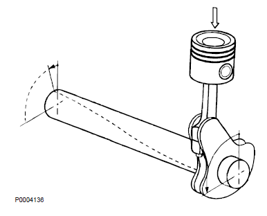
Torsional oscillations occur as a result of crankshaft forces caused by the pistons and connecting rods during the power stroke. These forces tend to bend the crankshaft and cause angular deflections.
• The frequency is crankshaft the crankshaft oscillation speed.
• Amplitude is crankshaft oscillation angular velocity.
• The critical rpm number is where shaft oscillation is at its most powerful and able to cause stress that exceeds the material's safety limit.
Torsional Vibration Approvals
The objective of calculating torsional oscillations is to determine the critical rpm points and to ensure that these critical rpm values are outside engine operating rpm (within +10 % to -5 % of the continuous rpm value). Disregarding engine and driven unit torsional compatibility can cause a overheated vibration damper. An overheated vibration damper will lead to sheared flywheel bolts and ultimately crankshaft failure. When selecting a generator - single or double bearing - Volvo Penta can assist with the torsion analysis. Volvo Penta provides input data for its engines on request.
It is the system designer's (OEM) responsibility to prepare a torsional vibration analysis for the installation. A list of approved combinations of engines coupled to single-bearing generators can be found under technical information; refer to the Sales Support Tool, Partner
Network.
Rule of thumb for when TVC calculations should be made
• When changing engines on older installations, (repowering).
• When adding equipment, e.g. auxiliary alternators or pumps driven by shafts external to the engine.
• When selecting new combinations, e.g. another type of alternator.
Torsional Analysis Data

Volvo Penta can carry out a torsion analysis based on necessary information from the customer. The following technical data is required to carry out torsion analysis:
A Make and type of engine:
B Maximum power take-off.
C Operating rpm range. Lowest to highest rpm, and whether rpm are variable or continuous.
D Coupling between engine and drive equipment.
Make and type of coupling.
Drawing and technical data, coupling.
E Moments of inertia for the part of the coupling bolted to the flywheel and the part attached to the pump.
F Maximum torque, coupling.
G Make and type of driven equipment.
H Drawing of entire shaft, with dimensions.
I Moments of inertia for the shaft and components attached to it.
J A general drawing is required for more complicated installations.
Most generator manufacturers provide shaft drawings for the calculation of torsional oscillations, which include moments of inertia, their location on the shaft, and shaft diameter.
Arrangement and Planning

Engine Room
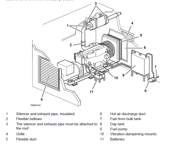
Typical engine compartment layout The illustration below shows a typical engine compartment
layout with an example of a single generator set installation. Hot air from the radiator must not be allowed to recirculate in the engine compartment, but must be led away in order for the temperature in the engine compartment to be kept as low as possible, so that the engine is able to provide the performance required. The exhaust system silencer must be attached to the roof and the attachment brackets must be able to expand with the exhaust pipes. A section of flexible pipe or a bellows must be installed between the exhaust discharge and the fixed pipe, especially if the generator set is on vibration dampening mounts. The exhaust system must be as short and have as few bends as possible in order not to exceed the recommendations regarding engine back pressure. If conditions result in a higher than recommended back pressure, a larger diameter exhaust pipe must be used to achieve the correct back pressure.
The same instructions apply to the hot air discharge line and all other engine and generator connections; these must be flexible (e.g. fuel pipes and electrical connections). The fuel day tank is supplied with fuel from a bulk tank located a long way from the engine. The fuel return from the engine must be led back to the bulk tank and not back to the day tank in order to avoid fuel overheating. Start batteries must be kept fully charged during idling periods by means of a tatic charger. The static charger may be included in the control panel.
For More Volvo Engine workshop information, please visit
Tools Used to Check Volvo Diesel Engine
General Information of Volvo Industrial Engines
Copyright © Guangxi Dingbo Generator Set Manufacturing Co., Ltd. All Rights Reserved | Sitemap
Update cookies preferences