Cooling Water System of Volvo Diesel Engine
Function
The function of the cooling water system is to transport heat energy away from the engine and accessory components to the radiator. The cooling water system consists of the coolant and the following components:
- Engine and radiator circuit
- Oil cooler circuit
- Charge air cooler circuit, water-to-air
- Expansion tank and venting circuit
The system can be extended with extra circuits:
- Torque converter oil cooler circuit
- Compressor cooler circuit
- Engine heater circuit
- Cabin heater circuit
- Coolant filter circuit
Coolant
From 2011, Volvo Penta will use the new type of coolant,VCS yellow.
The coolant has three functions:
1 To provide sufficient heat transfer.
2 To protect all cooling system metal parts from corrosion.
3 To provide sufficient protection against freezing. We recommend the use of “Volvo Penta Coolant, Ready Mixed” or “Volvo Penta Coolant” (concentrated) mixed with water. This is the only grade of coolant suitable for, and approved by, Volvo Penta. Anti-corrosion additives are not permitted in Volvo Penta engines. Never use water by itself as the coolant.
IMPORTANT! The correct mixture of coolant must be used all year round. This also applies where there is never a risk of freezing, to ensure that the engine has sufficient corrosion protection. Future warranty claims related to engine and accessories may be declined if an unsuitable coolant has been used, or if the recommendation for coolant mixture has not been followed.
Mixture ratio
WARNING!
All coolant is hazardous and harmful to the environment. Do not consume. Coolant is flammable.
IMPORTANT!
Under no circumstances may Volvo Penta coolant VCS, yellow be mixed with any other coolant.
IMPORTANT!
Industrial engines may not use coolant filters in combination with yellow VCS coolant. There filter is therefore not fitted to industrial engines filled with VCS yellow.
Mix:
40 % Volvo Penta glycol (conc. coolant)
60 % water
This mixture protects against internal corrosion, cavitation and damage from freezing down to -28 °C (-18 °F). The freezing point is lowered to -54 °C (-65 °F) with 60 % glycol in the coolant. Never mix more than 60 % concentrate (glycol) in the coolant, as this will impair protection against freezing, impair cooling ability, and result in a risk of overheating.
IMPORTANT!
The coolant must be mixed with clean water. Use distilled, deionized water. The water must comply with Volvo Penta requirements. Refer to Water Quality page 64.
IMPORTANT!
It is very important that the cooling system be filled with coolant of the correct concentration. Mix in a separate clean vessel before filling the cooling system.
Make sure the fluids are well mixed.
Engine and radiator circuit

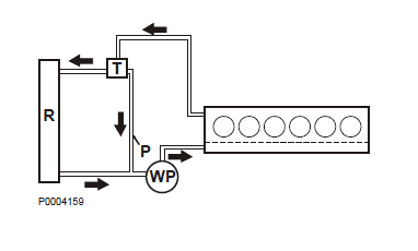
This circuit comprises the following main components:
- Thermostat (T)
- Coolant pump (WP)
- Water ducts in the engine block and cylinder heads
- A bypass (P) between the thermostat housing and the coolant pump
- Radiator (R)
- Pipes and hoses
The radiator may in certain cases be replaced with a heat exchanger of water-to-water type.
Certain engines also have a charge air cooler in the coolant circuit, e.g. TWD engines.
Coolant pump
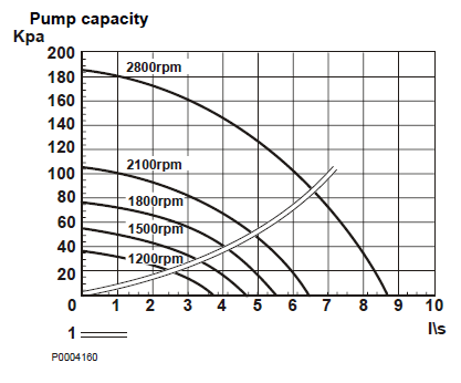
Coolant pumps are either belt or gearwheel-driven and are specially designed for each engine size. Pump rpm ratios for each engine are specified in the Sales Support Tool, Partner Network. The coolant pump is of centrifugal type in which oolant flow depends largely on system back pressure. If any accessory components are connected to the system, coolant flow will be reduced which means that consideration must be given to component pressure drop and the length, diameter and shape of pipes and hoses. The graph shows pump plots at different engine speeds. System coolant flow is determined at the intersection of the pump plot and the system plot, as described below. The following equations may be used to determine the pump plot for other engine speeds:

p2/p1 = (n2 / n1)2
qW2/qW1 = n2 / n1
p = static pressure (kPa)
qW = Coolant flow (I/s)
n = engine speed (rpm)
Use the values p1 and qW1 from a point on the existing engine speed plot n1. Calculate p2 and qW2 at the new engine speed n2 and plot this point in the graph. Repeat the procedure for a few other points on the n1 plot and draw the new pump plot through the calculated points.
The system plot describes the pressure drop through the system to which the coolant pump is connected.
The system plot uses the following formula:
p = k × qw
k = is a system-dependent constant and is used to draw the system plot as described in the instructions above.
The plot for the pressure drop (1) across the engine is drawn in the pump graph. This plot shows the pressure drop in the engine cooling ducts from the pump inlet to the upper engine outlet. The plot applies to a fully-open thermostat where the pressure drop across the oil cooler and a water-to-air charge air cooler (TWD engines) is included. The pressure drop across the external circuit must be added to engine pressure drop to determine the entire system plot. The external circuit usually comprises a radiator and hoses but there may also be a torque converter oil cooler.

The pressure drop across the components depends on coolant flow. System plot calculation is begun by calculating one point on the plot. The pressure drop across a Volvo Penta radiator for a given coolant flow can be obtained from Volvo Penta. The pressure drop across other components in the external circuit must be added to the pressure drop across the radiator at the same coolant flow. Add this sum to the pressure drop across the engine for the actual coolant flow in the pump graph. Now calculate the total pressure drop for a given coolant flow.
The full system plot (2) can now be drawn using the formula: p = k × qW 2.
Calculate k = p / qW 2 by using the values p and qW according to the instructions above.
System coolant flow (3) is determined at the intersection of the pump plot and the system plot for the actual engine speed. Outer cooling system flow restrictions must be checked on installations with accessory components installed in the liquid cooling system, or where there are long coolant pipes to remotely-installed radiators. The maximum flow restriction for the outer cooling system is specified in the Sales Support Tool, Partner Network.
For More Volvo Engine workshop information, please visit
Volvo Diesel Engine Installation and Cooling System
Volvo Engine Mountings for Mobile Installation
Copyright © Guangxi Dingbo Generator Set Manufacturing Co., Ltd. All Rights Reserved | Sitemap
Update cookies preferences