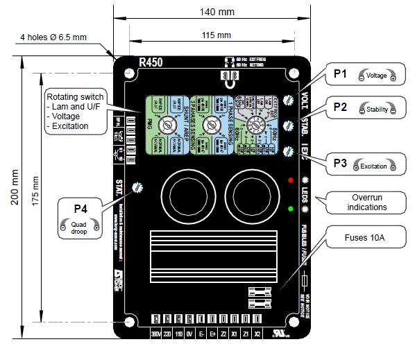
The R450 AVR is supplied in a casing designed to be mounted on a panel with dampers.
- Operating temperature: - 30°C to + 65°C.
- Storage temperature: - 55°C to + 85°C.
- Shocks on the base: 9 g depending on the 3 axes.
- Vibrations: less than 10 Hz, 2 mm half-peak amplitude 10 Hz to 100 Hz: 100 mm/s, above 100 Hz: 8 g.
The AVR is IP00, it must be incorporated in an environment which ensures it a IP20 protection.
The connection is realised by “Faston” connectors and the voltage sensing is single - phase.

Both the SHUNT/AREP & PMG excitation systems are controlled by the AVR.
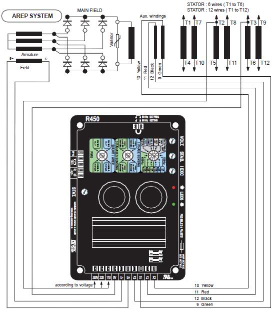
With AREP excitation, the electronic AVR is powered by two auxiliary windings which are independent of the voltage sensing circuit.
The first winding has a voltage proportional to the alternator main voltage (Shunt characteristic), the second one has a voltage proportional to the stator current (compound characteristic : Booster effect).
The power supply voltage is rectified and filtered before being used by the AVR monitoring transistor.
This system provides the machine with a short-circuit current capacity of 3 IN for 10 s. The rotating switch should be in the AREP position (see 3.2.3).

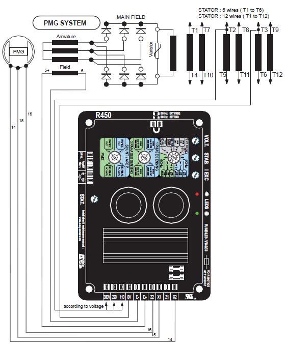
With PMG excitation, a permanent magnet generator (PMG) added to the alternator supplies the AVR with voltage which is independent of the main alternator winding.
This system provides the machine with a short-circuit current capacity of 3 IN for 10 s.
The AVR monitors the alternator output voltage by adjusting the excitation current. The rotating switch should be in the PMG position (see 3.2.3).

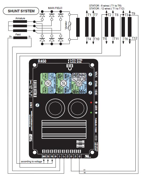
With SHUNT excitation, the AVR is powered by the main winding (100V to 140V -50/60 Hz ) by using X1, X2 on the AVR. The rotating switch should be in the SHUNT/ AREP position (see 3.2.3).

- maximum power supply: 150V - 50/60 Hz
- Rated overload current: 10 A - 10 s
- Electronic protection:
- In the case of a short-circuit, the excitation current is reduced to a value less than 1A after 10 s
- In the event of loss of voltage reference, the excitation current is reduced to a value less than 1A after 1s for AREP/SHUNT, 10 s for PMG.
- In the event of overexcitation, the current is reduced as indicated in the next diagram (see 3.2.1.4).
- Fuses: F1 on X1 and F2 on Z2 10A, 250V.
- Voltage sensing
• 0-110 V terminals = 95 to 140 V
• 0-220 V terminals = 170 to 260 V
• 0-380 V terminals = 340 to 528 V
For other voltages, a transformer should be used.
- Voltage regulation:± 0.5%.
- Current sensing: (parallel operation): input S1, S2 intended for 1 C.T. < 2.5 VA cl1, secondary 1 A or 5 A.
3.2.1 - Settings
3.2.1.1 - Voltage
Voltage adjustment via potentiometer P1 in the ranges described in the table below:
For 50 and 60 Hz | Max. |
High range | 320 V < Un ≤ 530 V |
Low range | 80 V ≤ Un ≤ 320 V |
Warning: The allowed adjustment range is ±5%; when the setting exceeds these limits, please check that it is conform with the power table.
3.2.1.2 - Quadrature droop
Quadrature droop adjustment via potentiometer P4 within a range:
- from 0 to 8% with a PF=0.8 for 400V applications.
- From 0 to 14% with a PF=0.8 for 240V applications.
- From 0 to 8% for 110V applications with a step-up transformer (ratio of 4) placed on the voltage reference.
The potentiometer P4 has a non linear response. Then, when a 1A secondary CT is connected the effective range starts from the the second 1/3 of P4 range and in the case of a 5A secondary CT the effective range starts from the first 1/3.
When a 5A CT is used, the adjustment range is higher, so P4 must be set to the first 1/4 (anti-clockwise) and then progressively increase it.
Warning: The CT must be connected.
3.2.1.3 - Stability
Stability adjustment via potentiometer P2. Selection of rotating switch according to the machine type and the response time as indicated in paragraph 3.2.3.
3.2.1.4 - Excitation limitation
Excitation limitation adjustment via potentiometer P3 as described below.
The excitation current limitation threshold in steady state is set by a potentiometer at 110% of the rated value. The adjustment is made by the operator during the on-load test at rated power by tuning the potentiometer. When the excitation current exceeds this value, a counter is activated at the speed of one record per second for 90 s. When this time is elapsed, the current is reduced to the value of the rated excitation current. If in the meantime the excitation current drops below the threshold value, the counter counts down at the same speed.
Maybe You Also Like: Introduction of Leroy-Somer Alternators
Copyright © Guangxi Dingbo Generator Set Manufacturing Co., Ltd. All Rights Reserved | Sitemap
Update cookies preferences