- Check that all connections have been made properly as shown in the attached wiring diagram.
- Check the rotating switches selections
- frequency,
- type of alternator,
- normal position (response time),
- external potentiometer,
- rated voltage,
- secondary current of the CT used,
- type of excitation.
- R450 optional operating modes
The various adjustments during tests must be made by a qualified engineer. It is essential that the drive speed specified on the nameplate is reached before commencing adjustment. After operational testing, replace all access panels or covers.
The AVR is used to make any adjustments to the machine.
Before using the AVR, make sure that the rotating switches have been correctly configured with AREP/SHUNT or PMG excitation
a) Initial potentiometer settings (see table below)
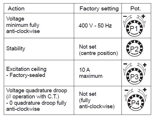
Stability adjustments in standalone operation
b) Install a D.C. analogue voltmeter (needle dial) cal. 100 V on terminals F+, F- and an A.C. voltmeter cal. 300 - 500 or 1000 V on the alternator output terminals.
c) Check the rotating switch selection.
d) Voltage potentiometer P1 at minimum, fully anti-clockwise.
e) Stability potentiometer P2 around 1/3 in from the anti-clockwise stop.
f) Start the engine and set its speed to a frequency of 48 Hz for 50 Hz, or 58 for 60 Hz.
g) Set the output voltage to the desired value using P1.
- Rated voltage UN for solo operation (eg. 400 V)
- Or UN + 2 to 4% for parallel operation with C.T. (eg. 410 V -)
If the voltage oscillates, use P2 to make adjustments (try both directions), observing the voltage between F+ and F- (approx. 10 V D.C.). The best response time is obtained at the limit of the instability. If no stable position can be obtained, try selecting the fast position.
h) Check LAM operation: depending on the rotating switch selection.
i) Vary the frequency (speed) around 48 or 58 Hz according to the operating frequency, and check the change in voltage from that observed previously (~ 15%).
j) Readjust the speed of the genset to its rated no-load value.
Adjustments in parallel operation Before starting work on the alternator, make sure that the speed droop is identical for all engines.
k) Preset for parallel operation (with C.T. connected to S1, S2)
- Potentiometer P4 (quadrature droop) in 1/4 position in the case of 5A CT and at 1/2 position in the case of 1A CT.
Apply the rated load (PF = 0.8 inductive). The voltage should drop by 2 to 3% (400 V). If it increases, check that neither V and W nor S1 and S2 have been reversed.
l) The no-load voltages should be identical for all the alternators intended to run in parallel.
- Couple the machines in parallel.
- By adjusting the speed, try to obtain 0 kW power exchange.
- By altering the voltage setting P1 on one of the machines, try to cancel (or minimise) the current circulating between the machines.
- From now on, do not touch the voltage settings.
m) Apply the available load (the setting is only correct if a reactive load is available)
- By altering the speed, match the kW (or divide the rated power of the units proportionally)
- By altering the quadrature droop potentiometer P4, match or divide the currents.
In standard setting, the potentiometer P3 is in maximum position.
However, for applications requiring an overload protection (see 3.2.1.4), the excitation ceiling must be adjusted by using the following procedures in AREP and PMG.
Method 1:
-Connect the AVR to the alternator
-apply load to 110% of rated machine rated at PF=0.8, the green led is on and the red one is off.
-record the excitation current value
-adjust P3 until obtaining the red led flashing, the green one is always on.
-decrease the load to 100% and make sure that the red led is off.
- Increase the load at 115%, check that the red LED flashes during 90 seconds and that the excitation current is brought back to the above adjusted value (Iex adjusted).
Method 2:
The rated excitation current (see machine plate) must be multiplied by 1.1 and the obtained value is used to set the potentiometer P3 at the right position.
The following table must be used.
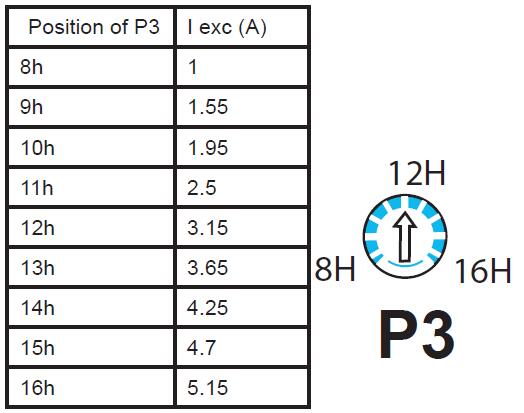
NB: In the case of a permanent short-circuit, the excitation current must reach 2.9 x Iex adjusted (limited to 9.5A), during 1 second in AREP or 10 seconds in PMG and shuts down to a value less than 1A.
Warning: When the excitation current is set to the rated value, a voltage dip is observed in excitation current limit when the limitation is activated and the current limit is reached.
Warning: The excitation circuit F+, F- must not be left open when the machine is running: this will irreparably damage the AVR.
4.2.3.1 - R450 (SHUNT) field weakening
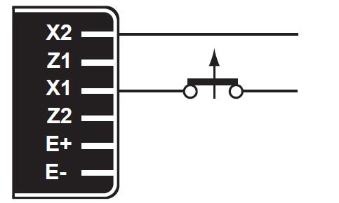
The exciter is switched off by disconnecting the AVR power supply (1 wire - X1 or X2) Contact rating: 16 A - 250 V A.C.
4.2.3.2 - R450 (AREP/PMG) field weakening
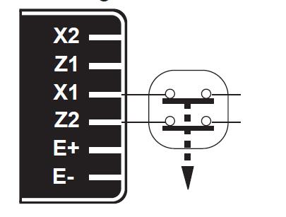
The exciter is switched off by disconnecting the AVR power supply (1 wire on each auxiliary winding) - contact rating 16 A - 250 V A.C.
Connection is identical for resetting the AVR internal protection.
Warning: If field weakening is used, provide field forcing.
4.2.3.3 - R450 field forcing
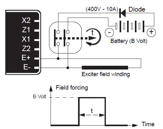
Applications | B Volt | Time t |
Guaranteed voltage build-up | 12 (1A) | 1 - 2 s |
Parallel operation, de-energized | ||
Parallel operation, at standstill | 5 – 10 s | |
Frequency starting | ||
Sustained voltage on overload |
Copyright © Guangxi Dingbo Generator Set Manufacturing Co., Ltd. All Rights Reserved | Sitemap
Update cookies preferences