There is no doubt that regular engine maintenance is very important to prolong the service life of a diesel generator. In this article, we mainly introduce the seasonal maintenance checks of Cummins generator.

Clean Cooling System (Autumn)
The cooling system must be clean to do its work properly. Scale in the system slows down heat absorption from water jackets and heat rejection from the radiator. Use clean water that will not clog any of the hundreds of small passages in the radiator or water passages in the block. Clean the radiator cores, heater cores, oil cooler and block passages that have become clogged with scale and sediment by chemical cleaning, neutralizing and flushing.
Chemical cleaning
If rust and scale have collected, the system must be chemically cleaned. Use a good cooling system cleaner and follow the manufacturer’s instructions.
Pressure Flushing
When pressure flushing the radiator, open the upper and lower hose connections and screw the radiator cap on tight. Use the hose connection on both the upper and lower connections to make the operation easier. Attach a flushing gun nozzle to the lower hose connection and let water run until the radiator is full. When full, apply air pressure gradually to avoid damage to the core. Shut off the air and allow the radiator to refill; then apply air pressure. Repeat until the water coming from the radiator is clean.
Caution: Do not use excessive air pressure while starting the water flow. This could split or damage the radiator core.
Sediment and dirt settle into pockets in the block as well as the radiator core. Remove the thermostats from the housing and flush the block with water. Partially restrict the lower opening until the block fills. Apply air pressure and force water from the lower opening. Repeat the process until the stream of water coming from the block is clean.
Replace Hose (As Required)
Inspect the oil filter and cooling system hose and hose connections for leaks and/or deterioration. Particles of deteriorated hose can be carried through the cooling system or lubricating system and restrict or clog small passages, especially radiator core, and lubricating oil cooler, and partially stop circulation. Replace as necessary.
Check Shutterstats and Thermatic Fans (Fall)
Shutterstats and thermatic fans must be set to operate in the same range as the thermostat with which they are used. Table 2-8 gives the settings for shutterstats and thermatic fans as normally used. The 180 to 195°F [82 to 91°C] thermostats are used only with shutterstats that are set to close at 187°F [86°C] and open at 195°F [91°C].
Check Thermostats and Seals (Fall)
Remove the thermostats from the thermostats housings and check for proper opening and closing temperature.
Most Cummins Engines are equipped with either medium 170 to 185°F[77 to 85° C] or low 160 to 175°F [71 to 79°C] and in a few cases high-range 180 to 195°F[82 to 91°C] thermostats, depending on engine application.
Steam Clean Engine (Spring)
Steam is the most satisfactory method of cleaning a dirty engine or piece of equipment. If steam is not available, use an approved solvent to wash the engine.
All electrical components and wiring should be protected from the full force of the cleaner spray nozzle.
Checking Mounting (Spring)
Tighten Mounting Bolts and Nuts (As Required)
Engine mounting bolts will occasionally work loose and cause the engine supports and brackets to wear rapidly. Tighten all mounting bolts or nuts and replace any broken or lost bolts or capscrews.
Table 2-9: Thermal Control Settings | ||||||
Control | Setting With 160 to 175°F [71 to 79°C] | Setting With 170 to 185°F [77 to 85°C] | Setting With 180 to 195°F [82 to 91°C] | |||
Open | Close | Open | Close | Open | Close | |
Thermatic Fan | 185°F [85°C] | 170°F [77°C] | 190°F [88°C] | 182°F [82°C] | ||
Shutterstat | 180°F [82°C] | 172°F [78°C] | 185°F [85°C] | 177°F [81°C] | 195°F [91°C] | 187°F [86°C] |
Modulating Shutters Open | 175°F [79°C] | 185°F [85°C] | 195°F [91°C] | |||
Torque Turbocharger Mounting Nuts (As Required)
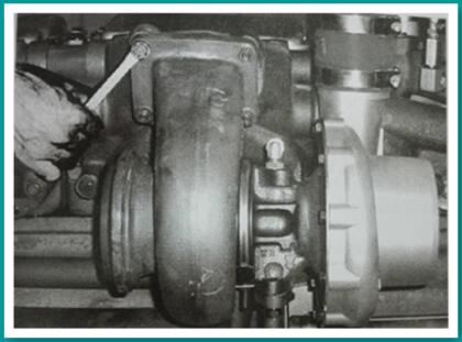
Torque all turbocharger mounting capscrews and nuts to be sure that they are holding security. Torque the mounting bolts and supports so that vibration will be at a minimum. Fig.2-24.

Fig.2-24. Tighten turbocharger mounting nuts.
Check Fan and Drive Pulley Mounting (Spring)
Check the fan to be sure it is securely mounted; tighten the capscrews as necessary. Check the fan for wobble or bent blades.
Check the fan hub and crankshaft drive pulley to be sure they are securely mounted. Check the fan hub pulley for looseness or wobble; if necessary, remove the fan pilot hub and tighten the shaft nut. Tighten the fan bracket capscrews.
Check Crankshaft End Clearance (Spring)
The crankshaft of a new or newly rebulit engine must have end clearance as listed in Table 2-9. A worn engine must not be operated with more than the worn limit end clearance shown in the same table. If the engine is disassembled for repair, install new thrust rings.
Table 2-9: Crankshaft End Clearance –Inch[mm] | |||
Engine Series | New Minimum | New Maximum | Worn Limit |
NT | 0.007 [0.18] | 0.017 [0.43] | 0.022 [0.56] |
Caution: Do not pry against the outer damper ring.
The check can be made by attaching an indicator to rest against the damper or pulley, while prying against the front cover and inner part of the pulley or damper. End clearance must be present with the engine mounted in the unit and assembled to the transmission or converter.
Check Heat Exchange Zinc Plugs (Spring)
Check the zinc plugs in the heat exchanger and change if they are badly eroded. Frequency of change depends upon the chemical reaction of raw water circulated through the heat exchanger.
Maybe You Also Like: How to Adjust Crosshead, Injector And Valves of Cummins NT Engines
Copyright © Guangxi Dingbo Generator Set Manufacturing Co., Ltd. All Rights Reserved | Sitemap
Update cookies preferences