This post is mainly written to introduce how to adjust crosshead, injector and valves of Cummins NT diesel engines correctly. Pay attention to reading and you will learn more.
Crosshead Adjustment
Note: Crosshead adjustment should always be made before attempting to adjust the valves.
1. Loosen the locknut on the crosshead adjusting screw. Turn the adjusting screw out at least one turn.
2. Hold the crosshead down against its mating valve stem. Turn the adjusting screw back in until it touches the valve stem. Hold the adjusting screw in this position and tighten the locknut.
3. Tighten the adjusting screw locknut to 25 to 30 ft-lb [34 to 41 N*m] torque.
Note: When ST-669 Torque Wrench Adapter is used, tighten the locknut to 22 to 26 ft-lb [30 to 35 N*m] torque.
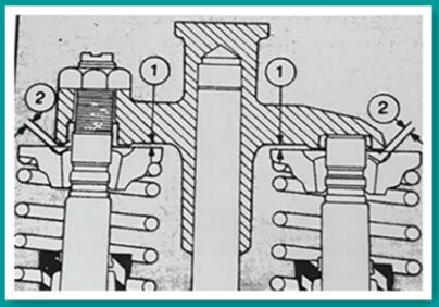
4. Check the clearance between the crosshead and valve spring retainer 1 and 2. Fig. 2-19 with a wire gauge. Tighten must be a minimum of 0.025 inch [0.64 mm] clearance.

Fig.2-19. Valve spring retainer to crosshead clearance.
Valve Adjustment
The “VS” markets used when adjusting the injectors is also used when adjusting the valves; however, the valves to be adjusted are not on the same cylinder as the injector. See Table 2-3 for the correct valves to adjust.
Example: When 1-6 “VS” is used, the injector on cylinder number 3 is adjusted and the valves on cylinder number 5 are adjusted.
1. Loosen both locknuts on the intake and exhaust valve adjusting screws.
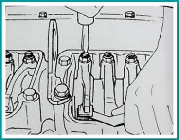
2. Insert the proper feeler gauge between the rocker lever and crosshead contact surfaces. (Fig.2-20). See Table 2-9 for valve clearance valves.
3. Turn the adjusting screw down until the rocker lever just touches the feeler gauge. Hold the adjusting screw in this position and tighten the locknut to 40 to 45 ft-lb [54 to 61 N*m] torque.
Note: When ST-669 Torque Wrench Adapter is used, tighten the locknut to 35 to 40 ft-lb [47 to 54 N*m] torque.
4. Always adjust the valves after the injector adjustment. Move to the next cylinder as indicated in Table 2-3 and repeat the adjustments until all injectors and valves have been set.

Fig. 2-20. Adjust valve clearance
Adjust Injector and Valves (Torque Method For Top-Stop Injector Engines)
Timing Mark Alignment
1. Loosen the injector rocker lever adjusting nut on all cylinders. This will aid in distinguishing between cylinders adjusted and not adjusted.
2. Bar the engine in the direction of rotation until a valve set mark aligns with the mark or pointer on the gear case cover.
3. Check the valve rocker levers on the two cylinders aligned as indicated on the pulley. On one cylinder of the pair, both rocker levers will be free and the valves closed; this is the cylinder to be adjusted.
4. Adjust the injector plunger first, then the crossheads and valves to the clearances indicated in the following paragraphs.
5. For the firing order see Table 2-5 for Inline Engines.
Table 2-5: Engine Order N-855 Engines | |
Right Hand Rotation | Left Hand Rotation |
1-5-3-6-2-4 | 1-4-2-6-3-5 |
6. Continue to bar the engine to the next “VS” mark and adjust each cylinder in the firing order.
Note: Only one cylinder is aligned at each mark. Two complete revolutions of the crankshaft are required to adjust all cylinders.
Injector Plunger Adjustment
The injector plungers must be adjusted with an inch-pound torque wrench to a definite torque setting. A torque wrench with a screwdriver adapter can be used for this adjustment.
Turn the crankshaft in the direction of rotation until one of the “VS” marks are aligned with the pointer. Check both of the cylinders indicated on the pulley to see which valve rocker levers, this is the cylinder to be adjusted.
1. Turn the adjusting screw down until the plunger contacts the cup and advance an additional 15 degrees to squeeze the oil from the cup.
2. Loosen the adjusting screw one turn; then using an inch torque wrench with screwdriver adapter tighten the adjusting screw to the valve shown in Table 2-6 and tighten the locknut to 40 to 45 ft-lbs [54 to 61 N*m] torque. If ST-669 Torque Wrench Adapter is used, torque to 30 to 35 ft-lbs [41 to 47 N*m].
Crosshead Adjustment
Crossheads are used to operate two valves with one rocker lever. The crosshead adjustment is provided to assure equal operation of each pair of valves and prevent strain from misalignment.
Table 2-6: Injector Plunger Adjustment – Inch-lbs [N*m] | |
Cold Set | Hot Set |
Aluminum Rocker Housing | |
72 [8.1] | 72 [8.1] |
Valve Adjustment
The same engine position used in adjusting the injectors is used for settings the intake and exhaust valves. Adjust the injectors and the valves on the same cylinder at the same time.
1. While adjusting the valves, make sure that the compression release, on those engines so equipped, is in the running position.
2. Loosen the locknut and back off the adjusting screw. Insert a feeler gauge between the rocker lever and crosshead. Turn the screw down until the lever just touches the gauge and lock the adjusting screw in this position with the locknut. Tighten the locknut to 40 to 45 ft-lbs [54 to 61 N*m] torque. When using ST-669 torque to 30 to 35 ft-lbs [41 to 47 N*m].
3. Always make final valve adjustment at stabilized engine lubricating oil temperature. See Table 2-7 for the appropriate valve clearances.
Table 2-7: Valve Clearances – Inch [mm] | |
Intake Valves Cold Set | Exhaust Valves Cold Set |
Aluminum Rocker Housing | |
0.014 [0.36] | 0.027 [0.69] |
Maybe You Also Like: Diesel Generator/Power Generator

Copyright © Guangxi Dingbo Generator Set Manufacturing Co., Ltd. All Rights Reserved | Sitemap
Update cookies preferences