EMS (Engine control system)
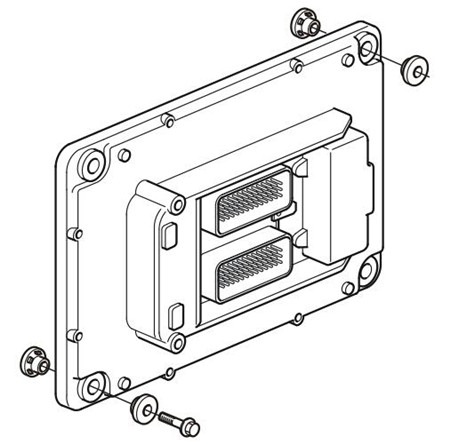
EMS 2 stands for “Engine Management System” and is an electronic system with CAN communications (Controller Area Network) for control of diesel engines. The system has been developed by Volvo Penta and includes fuel control and diagnosis function. The system consists of a control module, six unit injectors, a number of sensors that supply the control module with measurements, sockets for diagnosis and functional checks. The engine can be connected to a communication interface comprising a CAN-link and a serial link.
CAN (Controller Area Network)
The CAN J1939 link handles all communication between the engine control module EMS 2 and the CIU, in addition to the diagnostics that are handled by the so called J1708/J1587 link. The CAN link is much faster than the J1708/J1587 link. The CAN link has been prepared to connect to other components with SAE J1939 protocol such as instrument panels and transmissions.
If, for some reason, a fault develops on the CAN link, signals for the rpm-potentiometer and the start and stop knobs are taken over by the J1708/J1587 link. However, instrument and indicator lamps are completely turned off. If a fault occurs on both links, GE engines maintain engine speed, while VE engines go to idle. The only way to shut off the engine in this case is to use the auxiliary stop (AUX-STOP) placed on the engine’s left side.
CIU (Control Interface Unit)
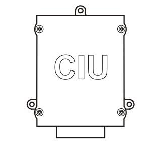
The CIU is a “translator” between the CAN bus and the customer’s own control panel. This unit has two serial communication links, one fast and one slow. The fast one is a CAN link that features a bus speed of 250 Kbit/ s. All data regarding instruments, indicator lamps, contacts and potentiometers are controlled by this bus.
The slower J1708/J1587 link handles diagnostic information for, among other things, the flashing code. The diagnosis tool VODIA also uses the J1708/J1587 link to communicate with the system.
Fuel control
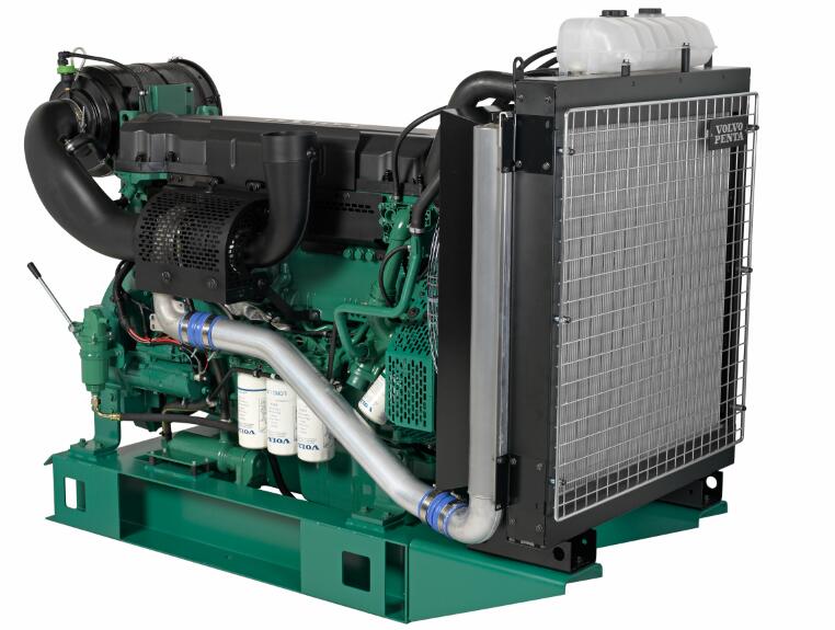
The engine’s fuel requirement is analyzed up to 100 times per second (depending on engine rpm). The engine’s injection amount and injection timing is controlled electronically via fuel valves on the unit injectors.
This means that the engine always receives the correct volume of fuel in all operating conditions, which offers lower fuel consumption, minimal exhaust emissions etc.
The control module checks and controls the unit injectors so that the correct amount of fuel is injected into each cylinder. It calculates and sets the injection angle. The control is primarily performed using the speed sensors and the combined sensor for boost pressure/charge air temperature.
The control module affects the unit injectors via an electronic signal to the unit injectors’ electromagnetic fuel valve, which can open and close.
When the fuel valve is open, fuel flows through the unit injector hole and out through the fuel channel. Fuel is not sprayed into the cylinder in this position. When the fuel valve closes, pressure starts to build from the unit injector’s mechanically operated pump plunger. When sufficient pressure has developed, fuel is injected into the cylinder via the unit injector’s injector section.
The fuel valve is re-opened and pressure in the unit injector decreases at the same time as the fuel injection to the cylinder stops.
In order to determine when the fuel valve shall open or close, the control module has access to signals from sensors and switch contacts.
Calculating fuel quantity
The amount of fuel that is sprayed into a cylinder is calculated by the control module. The calculation determines the time that the fuel valve is closed (when the fuel valve is closed fuel is sprayed into the cylinder).
The parameters controlling injected amount of fuel are:
• Requested engine speed
• Motor protector
• Temperature
• Boost air pressure
Altitude correction
The control unit is fitted with an atmospheric air pressure sensor and an altitude correction function for engines operating at high altitudes. This function limits the fuel volume in relation to ambient air pressure. This is to prevent smoke, high exhaust temperature and to protect the turbocharger from over-speeding.
Diagnosis function
The task of the diagnosis function is to detect and locate disturbances within the EMS 2 system, to protect the engine, and to provide information about problems that have developed. If a malfunction is dis-covered, this is announced by warning lamps, a flashing diagnostic lamp or in plain language on the instrument panel, depending on the equipment used. If a fault code is obtained as a flashing code or in plain language, this is used for guidance in any trouble-shooting. Fault codes can also be read by Volvo’s VODIA tool at authorized Volvo Penta workshops. In case of serious malfunctions, the engine is shut down completely, or the control unit reduces the power output (depending on application). A fault code is set as a guide when fault tracing.
In- and out signals
Information from the sensors provides accurate information regarding operational conditions and makes it possible for the control unit processor to calculate the correct injection amount, injection timing and engine condition, among many other things.
Input signals
The control unit receives input signals regarding engine operational conditions along with information from the following components:
- Coolant temperature sensor
- Charge air pressure/charge air temperature sensors - Crankcase pressure sensor
- Position sensor
- Camshaft
- Engine speed sensor
- Flywheel
- Piston cooling pressure sensor
- Coolant level sensor
- Oil pressure sensor
- Oil level and oil temperature sensors
- Fuel pressure sensor
- Water-in-fuel sensor
- Air filter pressure sensor
- Air temperature sensor
- Fan speed
Output signals
The control unit uses the input signals to control the following components:
- Unit injector
- Start motor
- Alternator
- Main relay
- Preheat relay
- Internal EGR (TAD1350-1355GE only)
- Waste gate
- Electronic fan control
DCU (Display Control Unit)
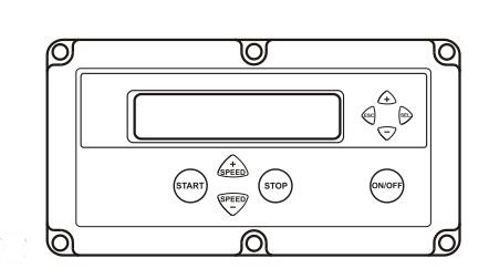
DCU is a digital instrument panel that communicates with the engine control unit via the CAN-link. DCU has several functions, such as:
Engine control
- Start, stop, rpm regulation, preheating, etc.
Monitoring
- Shows engine speed, charge pressure, charge temperature, coolant temperature, oil pressure, oil temperature, engine hours, battery voltage, instantaneous fuel consumption and fuel consumption (trip fuel).
Diagnostic
- Shows fault codes in text. Lists previous faults.
Parameter setting
- Idle speed, alarm limits for oil temperature/coolant
temperature, regulation mode (speed droop/isochronous).
DU (Display Unit)
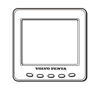
DU is an instrument for showing the engines operating values. The values are shown graphically on an LCD display. The display communicates via the CAN link and consists of a computerized unit for attachment to the control panel.
It is connected to the CAN link between the engine control unit and CIU or DCU.
Copyright © Guangxi Dingbo Generator Set Manufacturing Co., Ltd. All Rights Reserved | Sitemap
Update cookies preferences