More Information About Volvo Engine Measurements
Checking Crankshaft Sensor
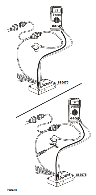
Tools:
885675 Break-out cable
88890074 Multimeter
1 NOTICE! Cut the current with the main switch.
2 Undo the connector from the sensor and remove the sensor from the cylinder head.
Check that the sensor does not have any external damage, or any swarf which has got stuck on it.
3 Connect break-out cable 885675 to sensor.
NOTICE! Do not connect the other end of the adapter cable to the engine cable harness, since this can cause a measurement error.
4 Use multimeter 88890074 for resistance measurement.
Measurement points | Nominal value |
1–2 | R ≈ 0,9 kΩ at 20 °C (68 °F) |
NOTICE! The measurement must exclude short circuit or open circuit to the engine control unit.
5 Use multimeter 88890074 for a AC voltage measurement.
Move a metal object rapidly back and forwards not more than 1 mm in front of the sensor. Check that the multimeter gives a reading.
6 Install the sensor.
Checking the CAN bus cable Communication fault J1939
Tools:
9990014 Break-out cable
9998699 Break-out box
88890074 Multimeter
The resistance of the CAN bus termination resistors, one 120 Ω resistor in the ECU and one 120 Ω resistor in the cable harness, are measured.
1 NOTICE! Cut the current with the main switch.
2 Disconnect the 8-pin Deutsch connector at the
DCU or disconnect at the CIU.
3 Use multimeter 88890074 to do resistance measurement towards the EMS 2.
Measurement points in the engine connector at the DCU | Nominal value |
1–2 | U ≈ 60 Ω |
or
Measurement points in the CIU connector | Nominal value |
11–12 | U ≈ 60 Ω |
NOTICE! Even if the measured value equals the nominal value the data bus cable could be faulty due to short circuit between a data bus cable and another cable in the harness.
1 Connect break-out cable 9990014 with break-out box 9998699 between the EMS2 connector B and the engine cable harness.
2 Use multimeter 88890074 to do a voltage measurement.
3 Turn ignition on.
Measurement points in the measurebox | Nominal value |
B51 (CAN H) – B58 (B-) | U ≈ 2.3–4.0 V |
B55 (CAN L) – B58 (B-) | U ≈ 1.0–2.5 V |
NOTICE! The voltage value fluctuates. If it is static it could indicate an open circuit.Even if the measured value equals the nominal value the data bus cable could be faulty due to short circuit between a data bus cable and another cable in the harness.
Checking the CAN bus cable Communication error
Tools:
88890074 Multimeter
88890016 Break-out cable
9998699 Break-out box
The resistance of the CAN bus termination resistors, one 120 Ω resistor in the ECU and one 120 Ω resistor in the cable harness, are measured.
1 NOTICE! Cut the current with the main switch.
2 Disconnect the 8-pin Deutsch connector at the
DCU or disconnect at the CIU.
3 Use multimeter 88890074 to do resistance measurement towards the EMS 2.
Measurement points in the engine connector at the DCU | Nominal value |
1–2 | U ≈ 60 Ω |
or
Measurement points in the CIU connector | Nominal value |
11–12 | U ≈ 60 Ω |
NOTICE! Even if the measured value equals the nominal value the data bus cable could be faulty due to short circuit between a data bus cable and another cable in the harness.
1 Connect break-out cable 88890016 with break-out box 9998699 between the EMS 2 and the CIU/
DCU.
2 Use multimeter 88890074 to do a voltage measurement.
Measurement points in the measurebox | Nominal value |
16 – 17 (between CAN bus) | U ≈ 2.3 V – 2.7 V |
NOTICE! Even if the measured value equals the nominal value the data bus cable could be faulty due to short circuit between a data bus cable and another cable in the harness.
Checking negative cable, coolant temperature sensor
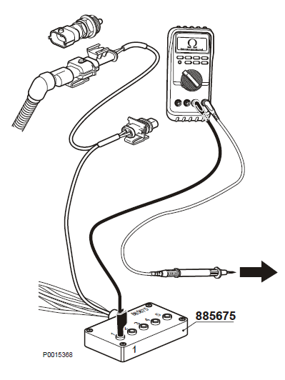
Tools:
885675 Break-out cable
88890074 Multimeter
NOTICE! If any of the measurements shows an abnormal value, check the wiring to and from the engine interface.
1 Cut the current with the main switch.
2 Disconnect the connector from the sensor.
3 Connect break-out cable 885675 to the cable harness connector to the engine control unit.
4 Use multimeter 88890074 to do resistance measurement towards the engine control unit.
Measurement points | Nominal value |
1 – Battery negative | R ≈ 0 Ω |
Checking signal cable, coolant temperature sensor
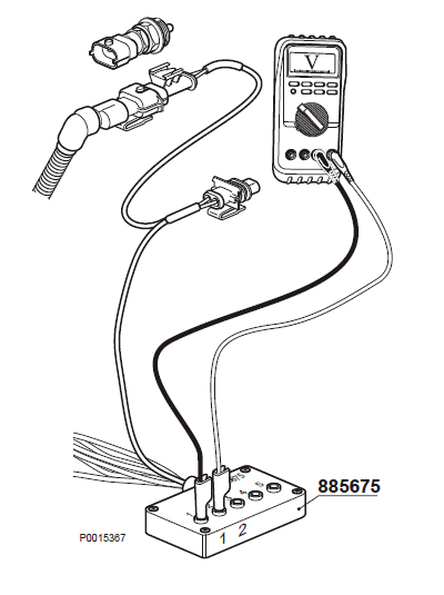
Tools:
885675 Break-out cable
88890074 Multimeter
1 Turn ignition on.
2 Disconnect the connector from the sensor.
3 Connect break-out cable 885675 to the cable harness connector to the engine control unit.
4 Use multimeter 88890074 for voltage measurement.
5 Turn ignition off.
Measurement points | Nominal value |
1–2 | U ≈ 5 V |
Checking sensor cable, coolant temperature sensor
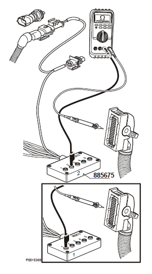
Tools:
885675 Break-out cable
88890074 Multimeter
Check for open circuit or short circuit
1 Cut the current with the main switch.
2 Disconnect the connector from the sensor.
3 Connect break-out cable 885675 to the cable harness connector to the engine control unit.
4 Remove connector B from the engine control unit.
5 Use multimeter 88890074 to do a resistance measurement against the engine control unit connector B.
Measurement points | Nominal value |
2 (885675) – 27 (EMS 2, conn.B) | R ≈ 0 Ω |
2 (885675) – 18 (EMS 2, conn.B) | R ≈ ∞ Ω |
1 (885675) – 27 (EMS 2, conn.B) | R ≈ ∞ Ω |
1 (885675) – 18 (EMS 2, conn.B) | R ≈ 0 Ω |
NOTICE! Measurement is done to eliminate short circuiting or breaks in the cable to the engine control unit.
Checking coolant temperature sensor
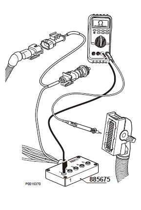
Tools:
885675 Break-out cable
88890074 Multimeter
1 NOTICE! Cut the current with the main switch.
2 Connect adapter cable (885675) to the sensor. Do not connect the other end of the adapter cable.
3 Use multimeter 88890074 to do resistance measurement.
Measurement points | Nominal value |
1–2 | R ≈ 9397 Ω +/- 755 Ω (at -10° C) |
1–2 | R ≈ 5896 Ω +/- 430 Ω (at 0° C) |
1–2 | R ≈ 2500 Ω +/- 148 Ω (at 20° C) |
1–2 | R ≈ 1175 Ω +/- 56 Ω (at 40° C) |
1–2 | R ≈ 596 Ω +/- 22 Ω (at 60° C) |
1–2 | R ≈ 323 Ω +/- 10 Ω (at 80° C) |
1–2 | R ≈ 186 Ω +/- 5 Ω (at 100° C) |
1–2 | R ≈ 113 Ω +/- 4 Ω (at 120° C) |
Checking supply cable, rail pressure sensor
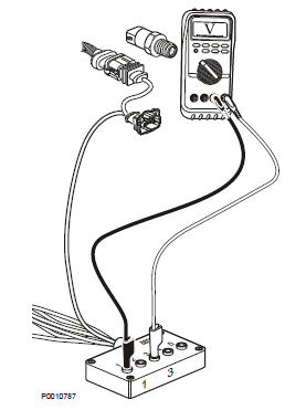
NOTICE! If any of the measurements shows an abnormal
value, check the wiring to and from the engine
interface.
1 Turn ignition off.
2 Disconnect the connector from the sensor.
3 Connect break-out cable 885675 to the cable harness connector to the engine control unit.
4 Use multimeter 88890074 for voltage measurement.
5 Turn ignition on.
Measurement points | Nominal value |
1–3 | U ≈ 5 V |
Checking negative cable, rail pressure sensor
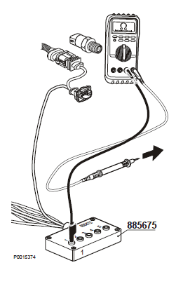
Tools:
885675 Break-out cable
88890074 Multimeter
1 Cut the current with the main switch.
2 Disconnect the connector from the sensor.
3 Connect break-out cable 885675 to the cable harnessconnector to the engine control unit.
4 Use multimeter 88890074 to do resistance measurement against the engine control unit.
Measurement points | Nominal value |
1 – Battery negative | R ≈0 Ω |
For More Volvo Engine workshop information, please visit
Volvo Diesel Engine Measurements
Engine Measurements-Checking Volvo Diesel Engine
Copyright © Guangxi Dingbo Generator Set Manufacturing Co., Ltd. All Rights Reserved | Sitemap
Update cookies preferences