The followings are the main instlaltion requirements for Yuchai YC4108D and YC4208ZD series diesel engines. Do read the requirements and instructions carefully to avoid mistaken operation.
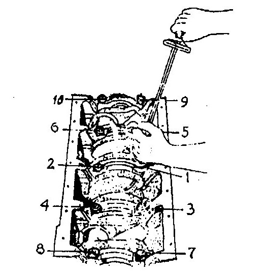
figure 1 Tightening order of the main bearings
During crankshaft installation, the main bearing bolts should be tightened from thrust gear ( the third gear) to both ends in order, and in three steps:
First, tighten t0 60 ~ 80N. m;
Then, tighten t0 160 ~ 180N. m;
Finally, tighten t0 220 ~ 260N. m.
During every time, the crankshaft should be rotated to check the mobility. It should be able to rotate freely after the final tightening. The axial clearance should be between 0. 1 and 0. 27mm.
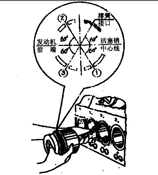
Figure 2 0rientation of the gap of piston rings
When installing; the piston rings, put the surfaces marked upward ( the second positive twist ring inner fillet upward) . During positioning the piston - connecting rod assembly into the cylinder bore, stagger the joints in tum as shown in Figure 2, and put the arrow marked on the top surface of piston towards the front end of the engine. Remember spreading some clean oil before tightening connecting - rod bolts. The tightening torque should be between 160 ~ 200N. m, and completed in three steps:
First, tighten to 50 ~ 70N. m;
Then, tighten t0 100 ~ 120N. m;
Finally, tighten t0 160 ~ 200N. m.
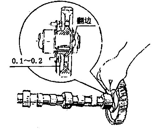
Figure 3 Camshaft axial clearances
Position the camshaft into the cylinder body with caution to make sure not scratch the surface of the journals, cams, and liners. And then install the circlip, cam thrust plate, cam gear, and cam retainer. Finally, tighten fastening bolt with more than 300N. m tightening torque. The camshaft should he able to rotate freely, and its axial clearance is between 0.1- 0. 2mm.
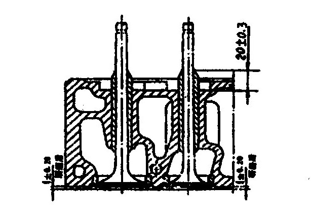
Figure 4 Installation of the valves and guides
The valve guides should be pressed in at normal state with 20±0.3mm distances between their top surfaces and the surfaces of the cylinder head spring seats. Both the valve face angles of intake and exhaust valves are 450. The valves and valve seat inserts should be grinded in pair, and checked through kerosene. It must he guaranteed that kerosene don’t leak within three minutes. The valve recession heights of the valves should be between 1±0.2mm.
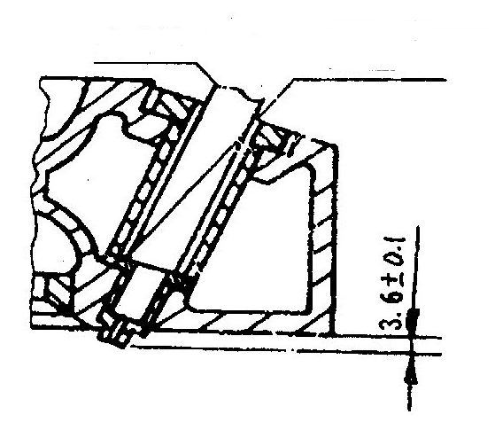
Figure 5 Installation of the injector
Before mounting the cylinder head, the injectors should be installed in the cylinder head first. The nozzles should protrude 3.4±0.1 mm from the bottom surface of the cylinder head, which can be ensured by adjusting the width of the injector washer. And then remove the injectors to prepare for following installation, As long as adjusted, the injectors and washers cannot be exchanged during installation.
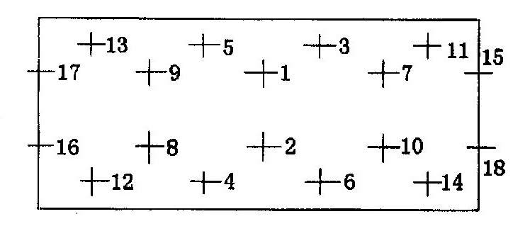
Figure 6 Tightening orders of the cylinder bolts
During cylinder head installation, the cylinder head bolts should be tightened to a tightening torque of between 210 ~ 250 N. m, don’t finish that in once time and following the sequence shown in Figure 6 in three steps:
First, tighten t0 60 ~ 80N. m ; .
Then, tif;hten t0 120 ~140N. m;
Finally, tighten t0 210 ~ 250N. m
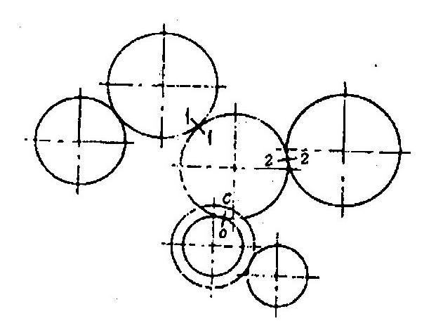
Figure 7 Installation of the gear system
The crankshaft timing gear, injection pump gear, and camshaft gear should all be accordance with the timing requirement, so there are timing marks, which should be aligned during installing the gears, on them and timing idle gear. Oil the tooth surface after installing. The range of try gear meshing clearance is between 0. 07 ~ 0. 25mm.
1. Every component should be cleaned before being installed, especially the oil passages, no dirt is permitted in them.
2. No corrosion, burr, or scratch is permitted on the fit surfaces of every component.
3. Friction surfaces and important fit surfaces should be oiled before installing.
4. Fit clearance ( or interference) should he accordance with the requirement offered in the main fit clearance ( or interference).
For more safety tips about YC4108d/YC4108ZD series:
YC4108D/YC4108ZD Series Diesel Engine-Cautions On Safe Driving
Copyright © Guangxi Dingbo Generator Set Manufacturing Co., Ltd. All Rights Reserved | Sitemap
Update cookies preferences