As we know that regular maintenance of engine is necessary and important. In this article, we mainly introduce the maintenance schedule of Volvo Penta power generation TD/TAD series engine.
Extended service intervals
The interval between engine oil changes may be extended in certain circumstances. To determine whether the service interval may be extended, Volvo Penta's conditions for extended service intervals must be met and an oil analysis performed. Contact your Volvo Penta dealer for further information.
Where both operational and calendar times are specified, perform the maintenance item at whichever time is the sooner.
Special Interval Service S1 - Every 125-500 Hours / at Least Every 12 Months(1)(2)
Special Interval Service S2 - Oil analysis.
Special Interval Service S3 - After the first 500 hours.
Type A service - Every 500 hours of operation.
Type B service - Every 1000 hours of operation.
Type C service - Every 1500 hours of operation.
Type D service - Every 2000 hours of operation.
Type E service - Every 8000 hours of operation
1) Oil change intervals vary, depending on oil grade and sulfur content of the fuel. Please refer to Oil recommendations.
2) Change oil filters every time the oil is changed.
Service Protocol
C = Clean
R = Replace
A – Adjustment
L – Lubrication
I – Inspection (includes, if necessary, cleaning, adjustment, lubrication and change)
S1
Every 125 -600 hours at least every 12 month | |
Engine Oil and Oil Filter/By-pass filer | R |
S2
Oil analysis | |
See dealer’s information | I |
S3
After the first 500 hours | |
Valve clearance | I |
A
Every 500 hours/ | At least every month | |||
12 | 24 | 48 | ||
Inspection with VODIA (Diagnostic Tool) | I | · | ||
Coolant level and antifreeze mixture | I | · | ||
Drive belts, belts tensioner and idle wheels | I | · | ||
Batteries, electrolyte level | I | · | ||
Air filter | I | · | ||
Fuel pre-filter, draining water/contamination | C | · | ||
Start and warm up engine | ||||
Engine and transmission, abnormal noises | I | · | ||
Engine and transmission, oil/fuel/water leakage | I | · | ||
1) Readout if any fault codes and LVD
B
Every 1000 hours/ | At least every month | |||
12 | 24 | 48 | ||
Fuel pre-filter, filter insert | R | · | ||
Fuel fine filter | R | · | ||
Air filter | R | · | ||
Engine and transmission, inspect hoses and cable clamping | I | · | ||
Engine and transmission, cleaning/painting | I | · | ||
C
Every 1500 hours/ | At least every month | |||
12 | 24 | 48 | ||
Valve clearance | I | |||
D
Every 2000 hours/ | At least every month | |||
12 | 24 | 48 | ||
Drive belts | R | · | ||
Air filter, Tank Breather | R | · | ||
Air filter, Compressor (Does not apply to all models.) | R | · | ||
AdBlue/DEF filter (Does not apply to all models.) | R | · | ||
Turbocharger, inspect/clean as required | I | · | ||
E
Every 8000 hours/ | At least every month | |||
12 | 24 | 48 | ||
Coolant VCR (yellow) | R | · | ||
1) Different type of coolant must not be mixed with each other.
Orientation
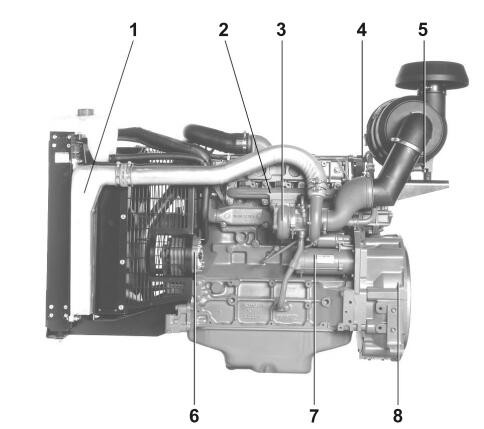
Examples of 5 -liter engines
1. Charge air cooler
2. Exhaust Manifold
3. Turbocharger
4. Closed crank case breather system 5 Air filter indicator
6. Alternator
7. Starter motor
8. Flywheel Housing SAE 3
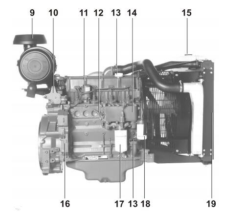
9. Air Filter
10. Fuel regulator
11. Stop solenoid
12. Coolant heater (option)
13. Engine Oil, Filling
14. Oil cooler
15. Expansion tank
16. Engine Transmission
17. Oil filter
18. Fuel Filter
19. Radiator
Examples of 6 and 7-liter engines
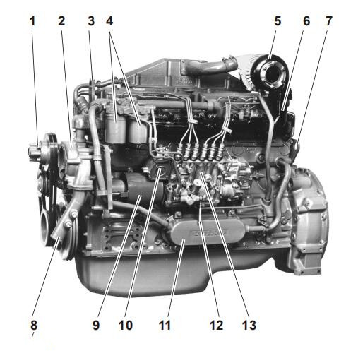
1 Fan hub
2 Coolant Pump
3 Lifting eye
4 Fuel Filters
5 Turbocharger
6 Exhaust Manifold
7 Lifting eye
8 Coolant inlet
9 Clutch protection
10 Smoke limiter
11 Oil cooler
12 Fuel line for tank connection
13 Injection Pump
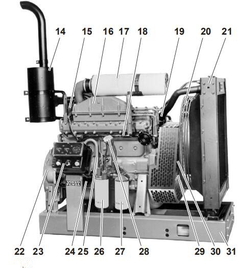
14 Silencer
15 Start Relay
16 Electrical starter element
17 Air Filter
18 Cable retrainer
19 Coolant pipe, outlet
20 Fan guard
21 Radiator
22 Flywheel housing
23 Instrument Panel
24 Starter motor
25 Crankcase ventilation
26 Lubricating oil filter, full flow
27 Lubricating oil filter, part flow
28 Oil filler cap, engine
29 Vibration Damper
30 Belt Tensioner (automatic)
31 Frame
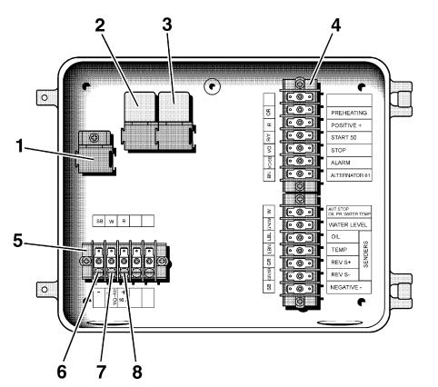
Instrument box
1. Location for level switch relay: coolant (accessory)
2. Relay for automatic stop: engine coolant temperature (ECT) switch, oil pressure switch and low coolant temperature switch (accessory)
3. Holding current relay (operating current and instruments)
4. Terminal block for engine cable harness
5. Terminal block for automatic stop and extra power output (maximum 16 A)
6. Negative (-) for extra power output (black cable)
7. Connection for any extra switches — automatic stop (white cable)
8. Positive (+) for extra power output (red cable). Maximum 16 A.
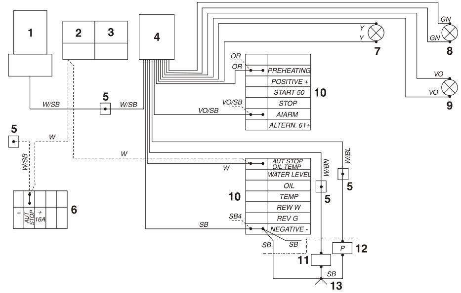
Alarm separator for the instrument box (accessory)
1. Relay for engine coolant level switch (accessory)
2. Relay for engine coolant temperature (ECT) switch, oil pressure switch
3. Holding current relay (operating current and instruments)
4. Alarm separator
5. Splice section
6. Terminal block for auxiliary power output (16 A fuse) and output for automatic stop, (closes in the event of a fault).
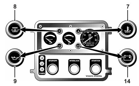
7. Warning lamp, high engine coolant temperature (accessory)
8. Warning lamp, low engine coolant level (accessory) 9 Warning lamp, low lubrication oil pressure (accessory)
10. Terminal block for engine cable harness
11. Engine coolant temperature (ECT) switch (normally open)
12. Oil pressure switch (normally open)
13. Joint splice
14. Warning lamp, generator not charging
Time relay kit for engagement of the starter (accessory)
1. Time relay
2. Connector. 8 pin
3. Ignition switch
4. Temperature switch (accessory)
5. Starter element
6. Indicator lamp (engaged starter element) 7 Battery
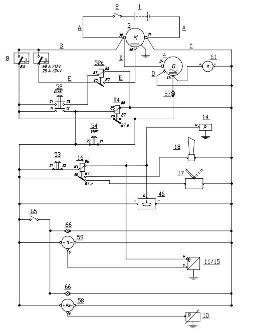
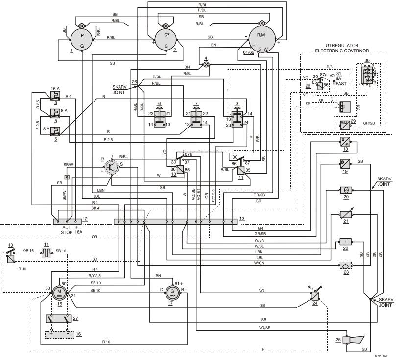
Wiring Diagram
Example (TD520GE, TAD720–21VE engines)
1. Battery
2. Main switch
3. Starter motor
4. Alternator
8. Fuse
10. Oil pressure sensor
11. Temperature Sensor/Engine connector
14. Oil pressure switch
15. Temperature Sensor/Engine connector
16. Relay
17. Stop solenoid
18. Horn
46. Water level sender (720)
52. Start button
52a. Start Relay
53. Interlocking button
54. Stop button
57. Charging lamp
58. Oil pressure sensor
59. Water temperature gauge
61. Hour Meter
65. Instrument light
66. Instrument light
84. Holding current relay
Example (6–7 liter engines)
Not for TAD720
1. Oil pressure gauge
2. Engine coolant temperature gauge
3. Tachometer with built-in hours run meter
4. Charge warning lamp
5. Semi-automatic fuse
6. Stop button
7. Interlocking button
8. Start button
9. Relay, Coolant Level (Accessory)
10. Relay, Coolant temperature/Oil pressure
11. Holding current relay (operating current and instruments)
12. Terminal block (auxiliary power output, with 16A fuse, output for automatic stop, closes in the event of a fault) 13. Relay, Starter element
14. Starter element
15. Starter motor
16. Batteries
17. Alternator
18. Engine speed sensor
19. Coolant temperature sensor
20. Coolant temperature (normally open)
21. Oil pressure sensor
22. Oil pressure switch (normally open)
23. Coolant level switch (Accessory)
24. Stop solenoid (current bearing during operation)
25. Horn
26. Joint splice
27. Main switch
28. Engine speed sensor
29. Relay
30. Engine speed governor
31. Fuse
*1 Remove when setting the UT governor
Maybe You Also Like: Volvo Penta Engine Operator Manual
Copyright © Guangxi Dingbo Generator Set Manufacturing Co., Ltd. All Rights Reserved | Sitemap
Update cookies preferences