Engine consists of two major mechanisms (crank linkage mechanism and valve mechanism) and five major systems (fuel supply system, cooling system, lubrication system, starting system and ignition system).
Includes body group, crankshaft flywheel group and piston rod group.
1. Body group
The block group is mainly composed of cylinder block, cylinder head, cylinder head gasket, oil sump, cylinder head cover and main bearing cap.
• Cylinder block, the main body of the engine, which connects each cylinder and crankcases, is the skeleton for mounting crankshaft, piston, and other parts and accessories.
According to the arrangement of cylinder block, it can be divided into three types: In- line, V type and horizontally-opposed type.
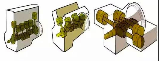
• Cylinder head, the function of the cylinder head is to seal the cylinder, form the combustion chamber with the piston, bear the high temperature and high pressure gas pressure, and is also the carrier of the valve distribution mechanism.
• Cylinder head gasket is also known as cylinder liner, located between the cylinder head and the cylinder block, its role is to ensure good sealing, prevent cylinder leakage and water jacket leakage.
• Oil sump is the lower half of the crankcase, also known as the lower crankcase. Its function is to seal the crankcase as the outer casing of the oil storage to prevent the entry of impurities.
• Cylinder head cover is located on the upper part of the engine. It is the cover that covers the cylinder head, which acts as a seal to prevent the entry of impurities.
2. Crankshaft flywheel group
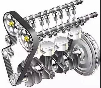
The crankshaft flywheel group is mainly composed of crankshaft, flywheel, crankshaft pulley and timing gear. It is mounted on the cylinder block.
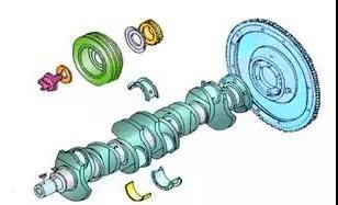
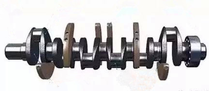
• Crankshaft bears the force from the connecting rod and converts the up and down motion of the piston into the rotational motion of the crankshaft and outputs.
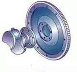
• Flywheel is mounted in the rear of the engine, and has a certain weight and function of energy storage. It is also the installation part of the clutch, and the gear ring on the clutch is the gear ring that drives the engine.
• Crankshaft pulley drives the power source of other engine accessories and relies on the transmission belt to transmit power to generators, pumps, compressors, directional power pumps and so on. The damping device is provided to reduce the shock vibration caused by the engine operation.
• The crankshaft timing gear transmits power to the timing gear of the camshaft to enable the engine to run stably.
3. Piston connecting rod group
The piston connecting rod group is mainly composed of piston, piston ring, piston pin, connecting rod, connecting rod bearing shell and connecting rod cover.
• Piston is a part of the reciprocating mechanism in the engine cylinder. The top of the piston is the main part of the combustion chamber.
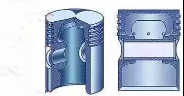
• Piston ring is embedded in the metal ring inside the piston groove. It is divided into gas ring and oil ring.
• The piston pin is used to connect the piston and the connecting rod to transmit the gas acting pressure on the piston to the connecting rod.
• The connecting rod connects the piston and the crankshaft, and transmits the force exerted by the piston to the crankshaft, turning the reciprocating motion of the piston into the rotational motion of the crankshaft.
• The connecting rod bearing bush is installed at the connecting part of the connecting rod and the crankshaft, which plays a role of wear resistance, connection, support and transmission, and there are oil holes on the tile wall.
• The connecting rod bearing shell is mounted on the connecting rod cover. The connecting rod is fixed on the crankshaft by connecting rod bolt.
• Connecting rod bolts play a role of locking the connecting rod cover and connecting rod.
Includes valve group and valve transmission group.
1. Valve group
The valve group mainly consists of valve, valve guide, valve oil seal, valve spring, valve spring seat and valve lock clamp.
• The valves seal the combustion chamber and controls the input of fuel and exhaust gas from the engine, which is divided into intake and exhaust valves.
• The valve guide is the guiding device of the engine valve, mounted on the cylinder head.
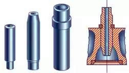
• The valve oil seal is used to seal the engine valve guide rod to prevent oil from entering the intake and exhaust pipes, causing oil loss.
• The valve spring ensures that the valve seats in time and fits closely to prevent the valve from bouncing during engine vibration, damaging its seal.
• The valve spring seat is divided into upper seat and lower seat. The main function is to apply the tension of the valve spring to the valve mechanism to ensure good airtightness between the valve and the valve seat.
• Valve lock clamp, in order to return the valve under the action of the valve spring, the valve lock clamp is required to catch the valve.
2. Valve transmission group
Valve transmission group is mainly composed of camshaft, valve tappet, valve top cup, valve rocker arm, rocker shaft, camshaft timing gear, valve push rod and so on.
The camshaft is provided with a cam to control the opening and closing of the valve.
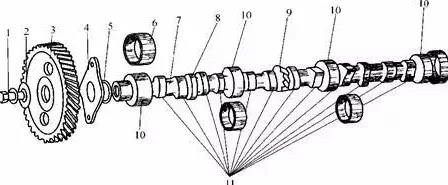
1) Bolt
2) Gasket
3) Time gear
4) Thrust flange
5) Flange seat
6) Camshaft bushing
7) Camshaft
8) Eccentric wheel of the drive gasoline pump
9) Helical gear of the drive distributor
10) Camshaft journal
11) Cam
• Valve tappets solve the impact and noise problems caused by valve clearance, controlled by oil pressure.
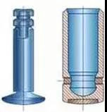
• Valve top cup is installed on the top of the valve, self-adjustable valve clearance (oil pressure control), also has the effect of reducing valve wear.
• Valve rocker arm transmits the force from the camshaft and controls the opening and closing of the valve.
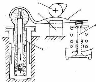
1 - Hydraulic tappet
2 - Guide groove
3 - Camshaft
4 - Floating rocker arm
5 - Valve
• Rocker shaft mounted the valve rocker arm around which the rocker arm rotates.

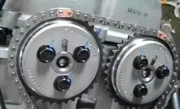
• Camshaft timing gear forces from crankshaft timing gear to drive camshaft timing gear through transmission belt (or chain) to transmit power to camshaft to control the normal opening and closing of valve.
• Valve pusher transmits the force from the camshaft to the rocker arm (Used for the camshaft center and the camshaft down).
Maybe You Also Like: What Are the Engine Performance Parameters
Copyright © Guangxi Dingbo Generator Set Manufacturing Co., Ltd. All Rights Reserved | Sitemap
Update cookies preferences