If you don't know how to operate Perkins generator 4006/4008 Series engines, this article will show you detailed information about Perkins lubrication system, cooling system and fuel system.
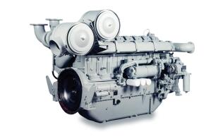
Preparation for install initial start batteries (Perkins batteries are supplied dry charged.)
Warning: Hand protection must be worn when checking electricity level in the battery. Inflammable gas is given off by the battery. Do not check with a naked flame.
Check the level of electrolyte In each of the battery cells; it should be 8-16 mm above the plates. Using a hydrometer, check that the batteries are fully charged. A fully charged battery will have a specific gravity of l.27 to 1,285, assuming the air temperature is below 32℃. For higher temperatures the specific gravity will be l.24 to 1.255. When topping up the batteries always use pure distilled water and always replace the plugs after filling.
Warning: Never connect a system without first checking the polarity and voltage. Never disconnect the battery whilst the engine is running. Never flash connections to check for current flow.
Filling the Engine With Oil
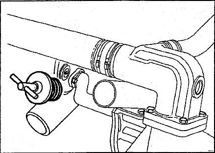
Remove the drain plug to ensure sump is clean and empty, refit and tighten the plug. Remove the oil filter plug situated on the left hand side of the gearcase by rotating T-bar anti-clockwise and pulling see Fig, 2.
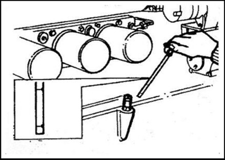
Fill the sump to maximum mark on the dipstick see Fig.3 with the appropriate grade and quality of oi! specified, and replace the plug, rotating the T-bar to tighten and seal it.
Priming the Lubrication System
Before starting the engine for the first time, or if it has stood idle for more than three months the crankshaft and turbocharger bearings should be primed.
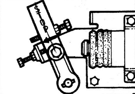
To prime the lubrication system the engine needs to be motored over on the starter. In order that the engine does not run up to speed when operating the key switch (i.e. energizing the stop solenoids) it will be necessary to hold the governor lever in the stop position (see Fig. 4).
Prime the lubricating system through the oil filters until approximately 0.3 bar (5lb/in) is indicated on the oi! pressure gauge. Continue pumping for a further 10 seconds to ensure that oil has reached the turbocharged.
Filling the Cooling System
The cooling system is pressurized - Do not remove the filler cap from the radiator whilst the engine is hot. Hand protection must be worn.
The use of plain drinking water is not recommended owing to chemical reactions which can result in corrosion and furring- up of the cooling system. A solution of either water and universal anti-freeze or water and corrosion preventative} must be used.
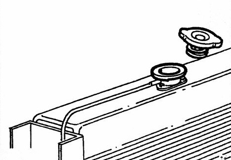
After installation and before the first start remove the radiator cap Fig. 5 by rotating it anti-clockwise. Fill the cooling system with the required coolant. Should the engine be fitted with water cooled exhaust manifolds then these may need bleeding. Run the engine off-load for one minute to ensure that the system is completely filled, then stop the engine and top up the system to 25 mm (1") below the top of the filter neck then replace the cap.
Preparation for Initial Start
Priming the Fuel System
Turn on the fuel feed from the day tank, loosen the union on the tee-piece (1) Fig. 6 then operate the priming pump by repeatedly pressing the rubber button (2) until air free fuel flows from the union , re-tighten the union .
Fuel flow circuit Fig. 6
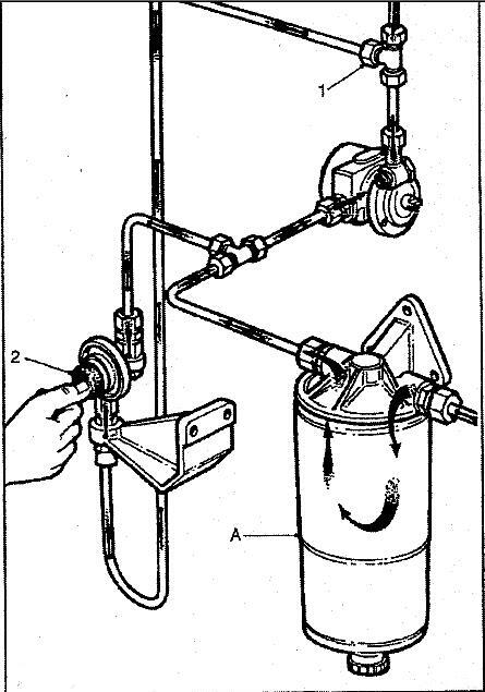
A. Combined fuel filter/water separator
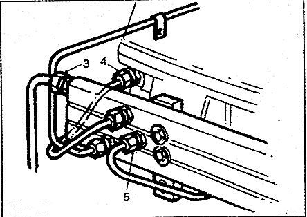
Loosen the union on the fuel feed pipe (3) Fig. 7 at the flywheel end of the fuel rail, Operate the priming pump until air free fuel flows and re-tighten the union , continue this operation at the fuel feed union (4) and the fuel return union (5) at this point one cylinder will be primed and a considerable amount of fuel will have reached other cylinders the engine will run in this condition if a little unevenly until air is fully vented from the system.
Optional Change Over Filter
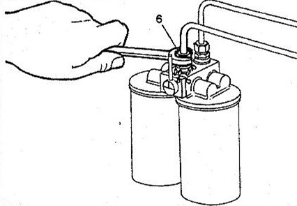
On engine fitted with a change over filter system prime the system as described above but prime the filter on the engine feed side union (6) Fig. 8 before priming the fuel rail.
Maybe You Also Like: Perkins Generator 4000 Series Engine Technical Data
Copyright © Guangxi Dingbo Generator Set Manufacturing Co., Ltd. All Rights Reserved | Sitemap
Update cookies preferences