DCU II (Display Control Unit)
The Volvo Penta DCU II instrument panel communicates with the engines control unit and has a number of functions as control, monitoring and diagnostics.
NOTICE! Settings and the type of engine data presented on the display may vary depending on the installation and engine model. Depending on the installation the DCU II can also be used as presentation display only.
NOTICE! The menus and illustrations shown here are the English version. Refer to the section Settingsto change the display language.
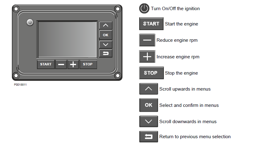
Display
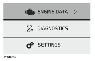
The DCU II basic view shows three main menus.
• VOLVO NGINE DATA (ENGINE DATA), shows current engine data.
• DIAGNOSTICS (DIAGNOSTICS), shows active fault codes.
• SETTINGS (SETTINGS), shows display and engine settings.
Status bar
The status bar with symbols for active malfunctions is shown in the top right of the display.
Alarms and messages
Messages to the operator are of three types, color coded according to degree of severity.
When a message is shown on the display, press OK key to reach the diagnostic menu to get more information regarding registered faults and instructions for remedial actions.
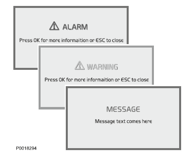
• ALARM (ALARM), red text, the system has detected a serious fault — consult a Volvo Penta workshop immediately.
• VARNING (WARNING), yellow text, the system has detected a fault — consult a Volvo Penta workshop as soon as possible.
• MEDDELANDE (MESSAGE), blue text, non-critical engine message for the operator.
Menus
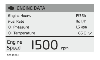
ENGINE DATA (ENGINE DATA)
Engine data shown may vary depending on the engine installation.
• Engine Hours (Engine Hour) (tim)
• Engine Speed (Engine Speed) (rpm)
• Coolant Temperature (Coolant Temperature) (°C)
• Oil Pressure (Oil Pressure) (kPa)
• Fuel Rate (Fuel Rate) (l/h) Current fuel consumption.
• Boost Temperature (Boost Temperature) (°C)
• Boost Pressure (Boost Pressure) (kPa)
• Oil Temperature (Oil Temperature) (°C)
DIAGNOSTICS (DIAGNOSTICS)
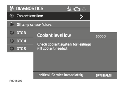
If the system detects a malfunction, the driver is informed via a pop-up message on the display. The fault codes are listed in the diagnostics menu; active fault codes are at the top of the list and are denoted be a green dot. For more information regarding cause and remedies, use the arrow button to scroll to the fault concerned and press OK . This will also provied information about number of engine hours when the fault became active and the SPN and FMI codes.
SETTINGS (SETTINGS)
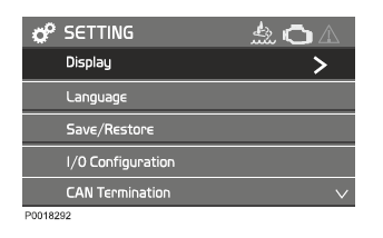
Display (Display)
• Set backlight time (Set backlight time). On/OFF, sets backlight to run in standby mode. On is the default setting.
• Set backlight brightness (Set backlight brightness). Adjust display backlight brightness using the panel arrow buttons.
• Set Instrument Brightness (Set Instrument Brightness). Sets backlighting in the display instrument.
• Change background color (Change background color). Select background color, gray or white.
Language (Language)
Sets the display language; chooses between English, French, German, Spanish and Chinese.
Save/Restore (Save/Restore)
• Save current configuration (Save current configuration). Save the current display settings.
• Restore last configuration (Restore last configuration). Restore the last displayed settings saved.
• Restore default configuration (Restore default configuration). Restores all display setting menus to factory settings.
IMPORTANT!
The settings in the following menus do not normally need to be changed; should a change be necessary it must be carried out by an authorized Volvo Penta technician. Refer to the installation manual for further engine information.
Authorized Volvo Penta dealer or OEM only
• I/O Status (I/O Status)
• CAN Termination (CAN Termination)
• Stop Logic DCU (Stop Logic DCU)
• Potentiometer supply (Potentiometer supply)
• Speed Control (Speed Control)
• Control display unit (Control display unit)
• Genset/VE (Genset/VE)
• Buzzer (Buzzer)
• Information (Information)
DU (Display Unit)
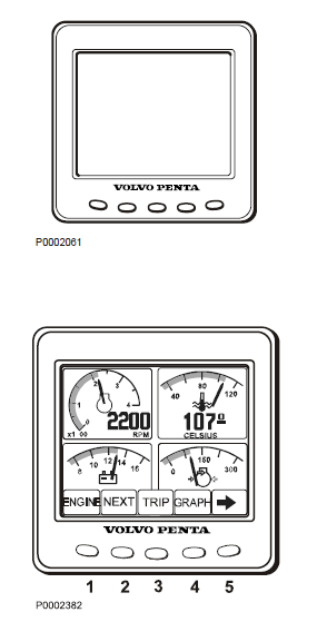
The DU is an computerized instrument panel which shows engine working values on an LCD screen. In the display it is possible to show multiple windows with different information, i. g. engine rpm, coolant temperature, fuel consumption and fault messages. At start up, the display performs a self-test. If an constant signal is heard, the system has discovered a malfunction. The display will work but may act in an unexpected way.
The DU is connected between the engine control unit and the CIU or DCU.
Display modes
Press any of button 1–4 to view the function menu for the buttons, apperaring in the lower part of the display. To leave the menu, wait a few seconds or press button
5 (EXIT).
1 Engine
2 Multi
3 Trip
4 Graph
5 Exit
Contrast
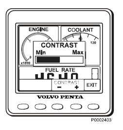
In the display modes Engine, Trip and Graph, it is possible to adjust the contrast.
Press button 5 outside the menu and then + (button 4) or – (button 3) to adjust the contrast.
Engine
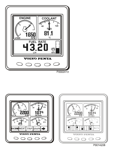
Rpm and coolant temperature is shown in the upper part of the display. In the lower part it will show trip computer and a fuel level indicator, if these function are installed.
Multi
In the multi mode, button 2, the information can be shown in four windows,analogue or digital. The display toggles between the two when button 2 is pressed repeatedly. By pressing button 5, the right arrow, you choose what information to be shown in the different windows. Press repeatedly on the button that correspond to the window, until desired information is shown.
Trip
To display the trip computer press button 3, Trip
Trip Fuel, since last reset
Fuel Rate, fuel consumption
Trip hours, since last reset
Engine hours, total amount of operating hours Reset by pressing button 3 for three seconds until a beep is heard.
Graph
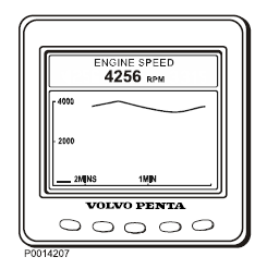
The information is shown as graphs. Press button 4 repeatedly to choose what information will be shown. The time interval is set in the Configuration menu. If the connection is broken there will be a straight line in the display.
Configuration menu
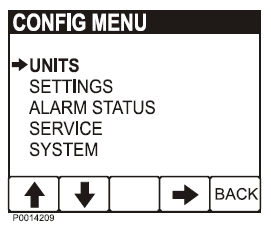
Press button 5 for three seconds to enter the Configuration menu. Navigate with the up and down arrows, select with the right arrow.
Units
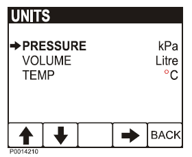
- PRESSURE; kPa, PSI
- VOLUME; LITRE, GAL, Imperial GAL.
Fuel rate is adjusted according to volume unit, L/H, GAL/H, IGAL/H.
- TEMPERATURE; °C, °F
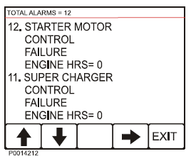
Alarm Status
List of active alarms, refer to Reading fault codes via the DU (Display Unit)
Settings
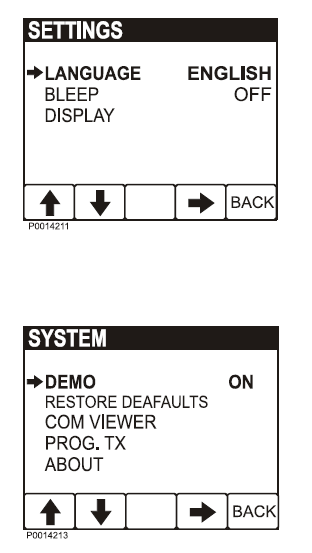
- LANGUAGE; setting of what language is to be used in the display.
- BLEEP; On/Off, setting if pressing the instrument buttons will be followed by a beep or not.
- DISPLAY; setting of ENGINE RPM gauges RPM ENGINE, 2500–9000 RPM, in steps of 500
RPM GRAPH RANGE, 2 minutes– 8 hours in the following steps, 2MINS, 10MINS, 30MINS, 60MINS, 2HRS, 4HRS, 8HRS
SYSTEM
- DEMO, switches the DEMO mode ON/OFF.
- RESTORE DEAFAULTS, reset all configuration to default values.
- COM VIEWER, displays latest message on communication ports
- PROG TX, transfers content of the application on Flash memory to other CAN units on the same CAN bus.
- ABOUT, displays
ID NO – display serial number
EEPROM – number of write on EEPROM
VERS – software version number
CHK – Flash memory checksum
PART No – Volvo software part number
SOURCE – source of received data
LABLE – Allocated Label on the same bus.
CIU (Control Interface Unit)
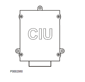
The CIU is a "translator" between the control unit (EMS) and the customer's own control panel. The CIU has two serial communication links, one fast and one slow.
The fast one is a so-called CAN link. All data related to instruments, indication lamps, connectors and potentiometers is controlled by this link.
The slow link manages diagnostic information for flashing codes etc.
Easy Link Instruments
The following Easy Link instruments are available:
- Tachometer / hours counter (fault codes are also displayed on the tachometer display when the diagnostic button is pressed)
- Coolant temperature
- Oil pressure
- Oil temperature
- Battery voltage
- Alarm panel
- Turbo pressure
For More Volvo Engine workshop information, please visit:
Volvo Engine Compressed Air Filter
Volvo Engine Instruments and Controls
Copyright © Guangxi Dingbo Generator Set Manufacturing Co., Ltd. All Rights Reserved | Sitemap
Update cookies preferences