Design and Function
EMS 2 (Engine Management System)
General Information
EMS 2 is an electronic system with CAN communication (Controller Area Network) for diesel engine control. The system has been developed by Volvo and includes fuel control and diagnostic function. The system consists of a control unit, six unit injectors, a number of sensors that supply the control unit with measurements, sockets for diagnosis and functional checks. The engine can be connected to a communications interface consisting of a CAN link and a serial link.
CAN - Controller Area Network
The J1939 CAN link is responsible after all communication between the engine control unit (EMS 2) and a communication interface (such as CIU/DCU), except for diagnostics. Diagnostics are managed by the socalled J1708/J1587 link. The CAN link is much faster than the J1708/J1587 link and has been designed to connect to other components that support the SAE J1939 protocol, such as instrument panels and transmissions. If a fault develops on the CAN link, signals for the
engine speed potentiometer, and the start and stop knobs are taken over by the J1708/J1587 link. However, instrument and indicator lamps are completely turned off.
If faults occur in both links, the engine starts to idle. The only way to shut off the engine in this case is to use the auxiliary stop (AUX-STOP).
CIU - Control Interface Unit
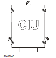
The CIU is a “translator” between the CAN bus and the customer’s own control panel. This unit has two serial communication links, one fast and one slow. The fast one is a CAN link that features a bus speed of 250 Kbit/s. All data regarding instruments, indicator lamps, contacts and potentiometers are controlled by this bus. The slower J1708/J1587 link handles diagnostic information for, among other things, the flashing code. The VODIA diagnosis tool also uses the J1708/J1587 link to communicate with the system.
DCU - Display Control Unit
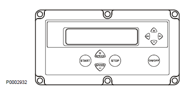
DCU is a digital instrument panel that communicates with the engine control unit via the CAN link. DCU has several functions, such as:
Engine control
- Start, stop, speed control, pre-heating etc.
Monitoring
- Engine speed, air inlet pressure, inlet manifold temperature, coolant temperature, oil pressure, oil temperature, engine hours, battery voltage, instantaneous fuel consumption and fuel consumption (trip fuel).
Diagnostics
- Shows fault codes in text. Lists previous faults. Parameter setting
- Idling speed, alarm limit for oil temperature/coolant temperature, droop.
- Preheating for ignition.
Information
- Information about hardware, software and engine identification.
Fuel control
The amount of fuel injected into the engine and the injection advance are fully electronically controlled, via fuel valves in the injectors, once the control unit has analyzed the engine’s fuel requirements. This means that the engine always receives the correct volume of fuel in all operating conditions, which offers lower fuel consumption, minimal exhaust emissions etc.
The control unit monitors and reads the injectors to ensure that the correct volume of fuel is injected into each cylinder, and it calculates and set the injection advance. Control is mainly done with the help of the speed sensors, fuel pressure sensor and the combined sensor for air inlet pressure/inlet manifold temperature. The control unit controls the injectors via a signal to the electromagnetically operated fuel valve in each injector, which can be opened and closed.
Calculation of fuel quantity
The quantity of fuel to be injected into the cylinder is calculated by the control unit. The calculation determines the time that the fuel valve is closed (when the fuel valve is closed fuel is sprayed into the cylinder).
The parameters which govern the amount of fuel injected are:
• Demanded engine speed
• Engine protector functions
• Temperature
• Air inlet pressure
Altitude correction
The control unit contains an atmospheric pressure sensor and an altitude compensation function for engines that operate at high altitude. This function limits the fuel volume in relation to ambient air pressure. This is to prevent smoke, high exhaust temperature and to protect the turbocharger from overspeeding.
Diagnostic function
The task of the diagnostic function is to discover and localize any malfunctions in the EMS 2 system, to protect the engine and to inform about any problems that occur. If a malfunction is discovered, this is announced by warning lamps, a flashing diagnostic lamp or in plain language on the instrument panel, depending on the equipment used. If a fault code is obtained as a flashing code or in plain language, this is used for guidance in any fault tracing. Fault codes can also be read by Volvo’s VODIA tool at authorized Volvo Penta workshops. In case of serious disturbances, the engine is shut down completely or the control unit decreases the power output (depending on the application). Once again, a fault code is set for guidance in any fault tracing.
Component description
Starter motor
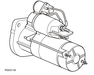
The starter motor is installed in the flywheel housing, on the left-hand side of the engine. The starter motor relay is "positive connected", which means that the relay is connected to battery voltage.
Alternator
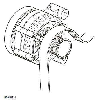
The alternator is belt driven and mounted on the front of the engine, on the right.
Injectors
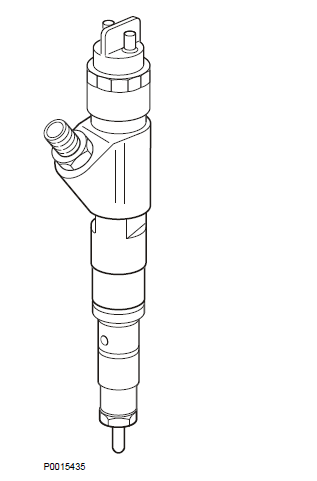
The injectors are installed on the cylinder head. The amount of fuel injected and injection duration is controlled by the engine control unit, via electromagnetically controlled fuel valves in the injectors. This means that the engine always receives the correct volume of fuel in all operating conditions, which offers lower fuel consumption, minimal exhaust emissions etc.
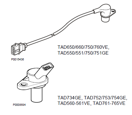
Speed sensor, crankshaft
The position sensor is located in the upper timing gear cover. The camshaft position sensor is of the inductive- sensor type. The sensor reads off a cogged wheel with 7 cogs. The impulses from the camshaft sensor give the control unit information about which cylinder is in turn for injection and when it is performed.
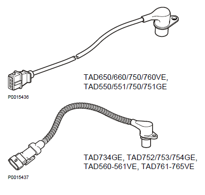
Speed sensor, camshaft (camshaft position)
The camshaft sensor is an inductive sensor. When the camshaft rotates impulses are created in the sensor via a tooth wheel installed on the camshaft. The tooth has seven teeth, one for each cylinder and one to determine when cylinder one is to be injected. The impulses create a pulse signal in the sensor that the engine control unit (EMS 2) uses to calculate when a cylinder is in turn for injection.
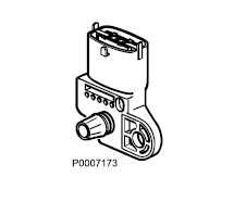
Air inlet pressure / inlet manifold temperature sensor
The air inlet pressure and the inlet manifold temperature are measured by a combined sensor located on the inlet manifold on the left of the engine. The sensor is supplied by a 5 Volt reference voltage from the engine control module. The air inlet pressure sensor measures the absolute pressure, which is the sum of the air inlet pressure and atmospheric pressure (300 kPa thus corresponds to a air inlet pressure of 200 kPa when atmospheric pressure is 100 kPa). The pressure signal is a voltage signal which is proportional to absolute pressure.
The inlet manifold temperature sensor consists of a non-linear resistor, whose resistance varies with inlet manifold temperature. The resistance falls as the temperature rises.
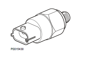
Sensor, oil pressure, engine
Oil pressure is measured by a sensor installed in the engine block on the right side of the engine. The sensor measures pressure in the main oil gallery, and is supplied by a 5 Volt reference voltage from the engine control module. The pressure signal is a voltage signal which is proportional to the lubrication oil pressure.
IEGR (only VE engines)
The IEGR valve is a 2-way solenoid valve controlled by the engine control unit. The IEGR solenoid controls a oil pressure that effects a control valve which activate the exhaust gas recirculation function.
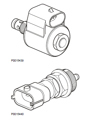
Coolant temperature sensor
The sensor is located on the cylinder head, at the rear end of the engine.
The sensor senses the engine coolant temperature and sends the information to the engine control unit.
The sensor consists of a non-linear resistor, whose resistance varies with coolant temperature. The resistance falls as the coolant temperature rises.
Sensor, common rail pressure (fuel)
The sensor is mounted on the right of the engine, at the front of the common rail, which distributes fuel to the injectors.
The rail pressure sensor senses the fuel pressure and converts this to a voltage which is registered by the engine control unit.
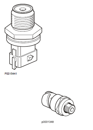
Fuel pressure sensor
The sensor measures fuel pressure and is located on the fuel filter bracket. The sensor is an active sensor, i.e. the sensor requires a supply voltage of +5 Volt. The sensor provides an output signal whose voltage is proportional to the pressure that the sensor measures.
Copyright © Guangxi Dingbo Generator Set Manufacturing Co., Ltd. All Rights Reserved | Sitemap
Update cookies preferences