Cooler e-EGR, change
TAD752GE, TAD753GE, TAD754GE
Removal
NOTICE! Be prepared to gather up fluids.
1 Drain the coolant entirely of sufficiently for the level to be below the e-EGR coolant pipe; refer to Coolant, Change page 187.
2 Remove the check valve according to Non-return valve e-EGR, change page 163.
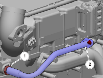
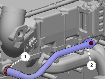
3 Remove the coolant pipe, outlet, from the e-EGR cooler.
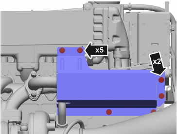
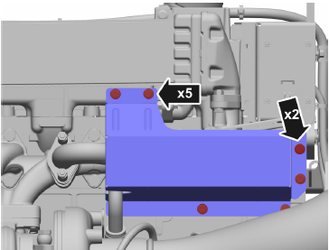
4 Remove the heat shield.
5 Remove the coolant pipe, inlet, from the e-EGR cooler.
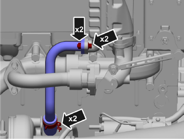
6 Remove the exhaust pipe and control valve; refer to Control valve e-EGR, change page 166.
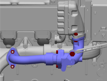
7 Remove the e-EGR and spacers.
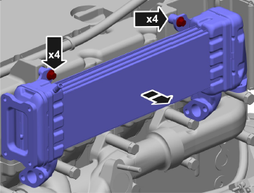
Installation
8 Fasten the cooler and spacers. Tightening torque: 20 Nm (14.8 lbf.ft.)
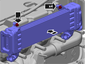
9 Install the exhaust pipe and e-EGR control valve according to Control valve e-EGR, change page 166.
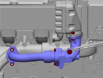
10 Install the coolant pipe, inlet, on the e-EGR cooler. Tightening torque: 20 Nm (14.8 lbf.ft.)
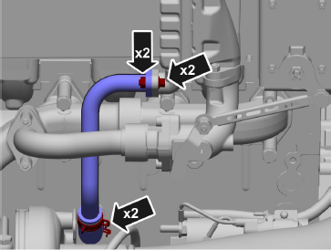
11 Install the coolant pipe, outlet, on the e-EGR cooler.
12 Install the check valve according to Non-return valve e-EGR, change page 163.
13 Fasten the heat shield. Tightening torque: 20 Nm (14.8 lbf.ft.)
14 Top up with coolant; refer to Coolant Level, Checking and Topping Up page 185.
15 Start the Volvo engine and check for leaks.
Non-return valve e-EGR, change
TAD752GE, TAD753GE, TAD754GE
Removal
1 Remove the e-EGR check valve and pipe.
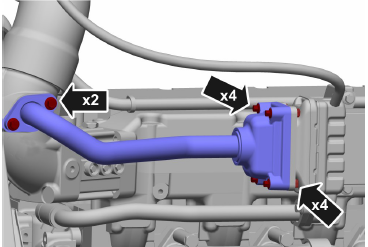
2 Move the pipe and check valve upward. Turn the pipe outward.
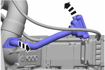
3 Pull out the pipe from the check valve. Remove the O-ring.
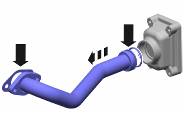
4 Remove the check valve.
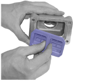
Installation
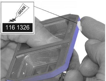
5 Brush a thin coating of silicone grease (part no. 1161326) around the lip of the check valve.
6 Slide the check valve into the housing.
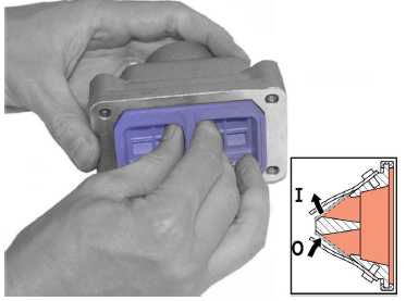
7 Lubricate the O-ring with silicone grease and press the pipe into the housing.
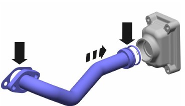
8 Press the check valve and pipe with a twisting motion until the contact surfaces mate.
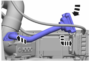
9 X4 nuts and bolts, tightening torque: 8.5 Nm (6.3 lbf.ft.)
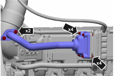
10 X2 bolts, tightening torque: 20 Nm (14.8 lbf.ft.)
Control valve e-EGR, change
TAD752GE, TAD753GE, TAD754GE
Removal
1 Remove the heat shield.
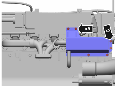
2 Remove the exhaust pipe, e-EGR.
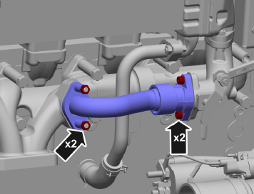
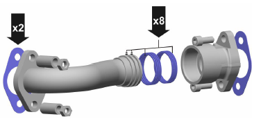
3 NOTICE! Use new seals when dismantling exhaust pipe e-EGR.
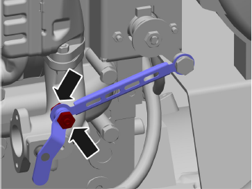
4 Undo the connection between the control arm and the control valve arm.
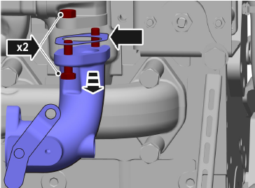
5 Remove the control valve.
Installation
NOTICE! Clean the sealing surfaces.
NOTICE! Use new seals.
6 Install the control valve.
Tightening torque: 20 Nm (14.8 lbf.ft.)
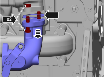
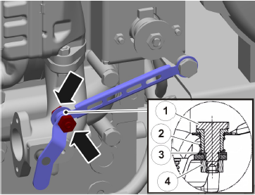
7 Connect the control arm, slide the bolt (1) through the sleeve (3) with spring (2); tighten using nut (4). Tightening torque: 20 Nm (14.8 lbf.ft.)
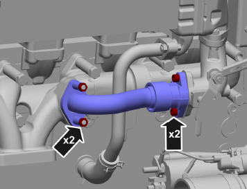
8 Install the exhaust pipe e-EGR. Tightening torque: 20 Nm (14.8 lbf.ft.)
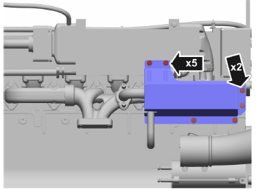
9 Fasten the heat shield.
Tightening torque: 20 Nm (14.8 lbf.ft.)
Actuator e-EGR, change
TAD752GE, TAD753GE, TAD754GE
Removal
NOTICE! The main switch must be in the off position before work is begun.
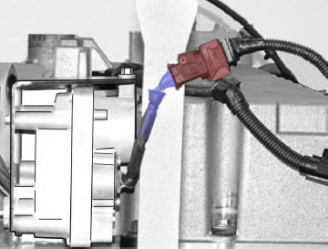
1 Remove the harness terminal from the actuator.
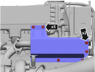
2 Remove the heat shield.
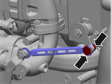
3 Disconnect the control arm from the actuator.
4 Remove the actuator.
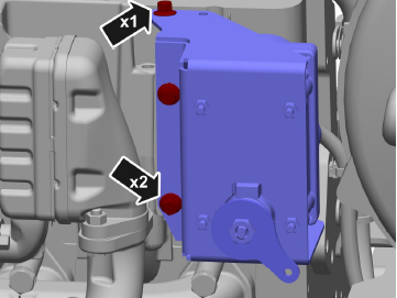
5 Remove the attachment bracket from the actuator.
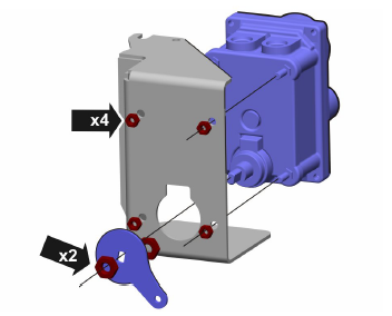
Installation
6 Fasten the actuator to the attachment bracket using nuts.
Tightening torque: 8.5 Nm (6.3 lbf.ft.)
7 Screw the nut until the end position on the shaft. Install the lever. Tighten the nuts.
Tightening torque: 15 Nm (11.1 lbf.ft.)
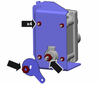
8 Install the actuator.
Tightening torque: 20 Nm (14.8 lbf.ft.)
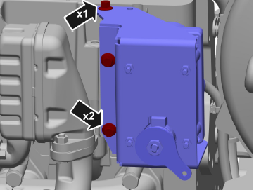
9 Connect the control arm to the actuator with a nut and bolt.
Tightening torque: 20 Nm (14.8 lbf.ft.)
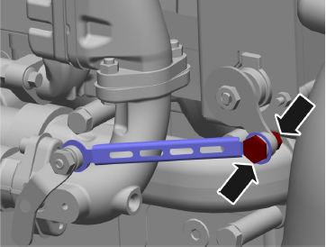
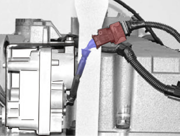
10 Connect the harness terminal to the actuator.
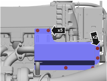
11 Install the heat shield.
Tightening torque: 20 Nm (14.8 lbf.ft.)
12 Turn the main switch on.
Turbocharger, Inspection
TAD752GE, TAD753GE, TAD754GE
1 Check that the turbocharger part number is correct for the engine variant. The wrong turbocharger for the engine variant might not provide enough charge pressure, which would reduce engine power.
2 Check that the turbocharger has the correct compressor housing. If the wrong compressor housing is installed on the turbocharger, the compressor wheel may be damaged or have excessive clearance between turbine wheel and housing. In both cases, charge air pressure will be too low.
3 Remove the inlet manifold from the turbocharger.
4 Check the turbocharger for damage to the compressor wheel and excessive end float on the turbine shaft.
5 If there is any damage on the compressor wheel or excessive end float on the turbine shaft, the
turbocharger must be changed as a unit.
6 Remove the exhaust pipe (silencer) from the turbocharger and check the turbine wheel.
7 Inspect the turbine wheel for damage. If the turbine wheel is damaged, the turbocharger must be changed as a unit.
Turbo, Change
TAD550GE, TAD551GE, TAD750GE, TAD751GE
Exhaust pipe removed.
Removal
1 Remove the intake pipe.
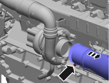
2 Remove the charge air pipe to the charge air cooler.
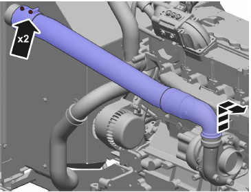
3 Remove the oil delivery pipe (1) and the oil return pipe (2).
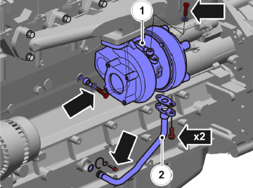
4 Remove the turbocharger and gasket.
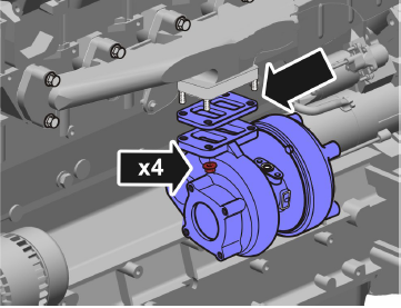
Installation
5 Install the turbocharger with a new gasket.
Tightening torque: 30 Nm (22.1 lbf. ft.)
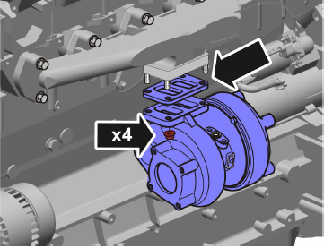
6 Install the turbocharger oil delivery pipe (1).
Tightening torque: 39 Nm (28.8 lbf. ft.)
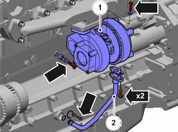
7 Install the turbocharger oil return pipe (2).
Tightening torque: 20 Nm (14.8 lbf. ft.)
8 Install the charge air pipe.
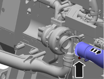
9 Install the inlet pipe.
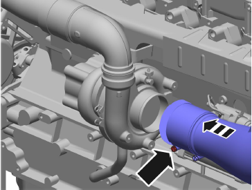
10 Check function.
Turbo, Change
TAD752GE, TAD753GE, TAD754GE
Exhaust pipe removed.
Removal
1 Remove the intake pipe.
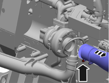
2 Remove the charge air pipe to the charge air cooler.
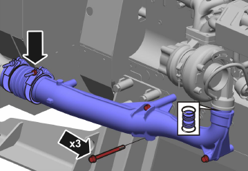
3 Remove the oil delivery pipe and the oil return pipe.
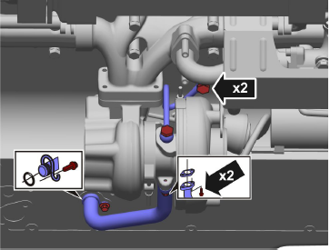
4 Remove the turbocharger and gasket.
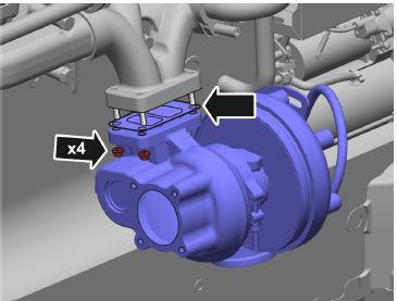
Installation
5 Install the turbocharger with a new gasket.
Tightening torque: 40 Nm (29.5 lbf. ft.)
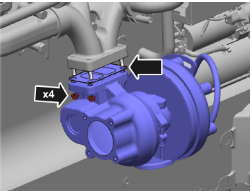
6 Install the turbocharger oil delivery pipe (1).
Tightening torque: 39 Nm (28.8 lbf. ft.)
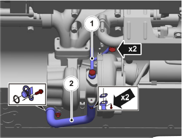
7 Install the turbocharger oil return pipe (2).
Tightening torque: 30 Nm (22.1 lbf. ft.)
8 Install the charge air pipe.
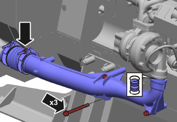
9 Install the inlet pipe.
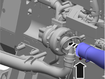
10 Check function.
Copyright © Guangxi Dingbo Generator Set Manufacturing Co., Ltd. All Rights Reserved | Sitemap
Update cookies preferences