Correct delivery beginning can enable the enable to obtain good performance. The crankshaft angle car/be determined by measuring the displacement which the piston from TDC, also it can be done by making use of the flywheel mark. It is recommended to use the former method for more precision.

When determining with the piston displacement, you should:
(1) Turn the crankshaft to let the piston of cylinder next to the gear-case end at TDC position of compression stroke ( the intake & exhaust valves are all closed) .
(2) Dismantle the rocker seat.
(3) Dismantle the valve spring of intake valve or exhaust valve. The valve head falls on the piston in the meantime.
(4)Set the dial gauge I with clamp at the top of valve stern. ( see Fig. 17 )
(5)Tum the crankshaft along CW and CCW directions to measure the position of piston at TDC, and dial the hand of dial gauge to 0 graduation.
(6) Turn the crankshaft along the contra0' direction to its working direction, and let the valve drop to not more than 15mm.
(7) Pull control handle 4 to the middle position.
(8) Dismantle the delivery valve 5 0f injection pump and mount the overflow pipe 6.
(9)Get rid of the air in fuel piping with the hand pump of delivery pump until no bubble spills from the overflow pipe.
(10) Pay attention to the moment of fuel dropping from overflow pipe while turn the crankshaft slowly along its working direction, Stop turning crankshaft as soon as the dropping occurs, and the crankshaft angle is the very position of delivery beginning for this cylinder. The delivery beginning angle can be found in the relationship between crankshaft angle and piston displacement (see Appendix I) by comparing it with indicated value on the dial gauge.
(11) Adjustment should to be done, if the measured angle differs from the required fuel supply advance angle, which in the fuel system matching table.
Note: the valve might fall down into the cylinder if the measured angle is too big when the crankshaft is turned. In order to prevent this situation occurring, clamp ring can be mounted in the groove of valve stem.
Examining by the flywheel mark:
There are TDC sign and scale on the circumferential of the flywheel. For the scale on the circumference of flywheel, you can read it via the side window 2 on the flywheel housing and the pointer.
( 1) Get rid of the air in fuel piping.
(2) Loosen the connecting nut between the high - pressure pipe and fuel pump at the gear end, divorce the high pressure pipe from fuel pump.
(3) Turn the crankshaft along working rotating direction and make the piston of 1st cylinder (flywheel end) at compression stroke, when turning continuously near delivery beginning, you should slow down and observe the fuel level from the port of delivery valve holder, stop turning as soon as the level rises. Read the degree of the angle scale before TDC from the fly-wheel, adjustment should be done to the fuel supply advance angle if the degree is out of standard.
Loosen the tightening nut of the injection pump flange, and tum the pump. The fuel supply advance angle increases when the top end of injection pump is turned towards cylinder block, and the angle decreases when doing in reverse. Check according to the above method after adjusting, and readjust until the advance angle meet the stated requirement.
The fuel supply advance angles for different model of diesel engine are listed in Fuel System Matching Table.
Injector assembly:
BOSCH S type nozzle is adopted for the diesel engine. See Fuel System Matching Table for details.
The fuel rough filter should be set before the fuel entering into delivery pump from fuel tank to protect the delivery pump and the fuel fine filter.
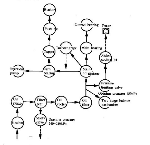
The schematic diagram for lubricating system:

The lubricating system consists of strainer, oil pump, oil cooler, oil filter and pressure limiting valve etc.
The strainer is the intake opening of the oil pump, the connection between it and the inlet of oil pump is sealed by 0 - ring, and special attention should be taken to avoid leakage during installing the connector, otherwise the air sucked in the oil pump will influence oil supply so as to result in severe accidents like bearing burning and engine damage. The oil pump is of gear pump. The pumped oil from oil pump enters into the filter seat which has a safety valve ( opening pressure is 540 - 750kPa) on it. The oil will be vented to oil sump when the pressure of oil pumped from oil pump exceeds the opening pressure value of safety valve. There are sockets on the filter seat for pressure sensor and oil cooler. The oil cooler is connected in series with the oil filter at the filter seat. The oil enters the oil cooler from filter seat, through the oil filter and returns the filter seat, then enters the main oil passage. Each finned oil cooler has 9 cooling chips, according to the actual need of different model. only one cooler can he used for the engine, also two coolers can he used in series. If the engine - mounted oil cooler cant meet the requirement of oil cooling for the engine, user may adopt out - connected cooler, but the filter seat 12273108 with oil inlet & outlet joints should be used instead of the former seat. The oil filter is of spin - on type, and can be used only once. In the lubricating system, pressure lubrication is adopted for the main bearing, connecting rod bearing, cam bearing, two stage balance mechanism bearing, rocker bearing, injection pump, turbocharger etc., and splash lubrication is adopted for the connecting rod small end, gear train, piston, cylinder liner etc.
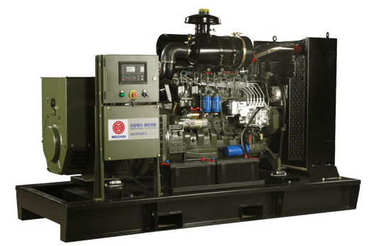
We supply 24KW to 500KW Deutz diesel generator set with Deutz engine.
Copyright © Guangxi Dingbo Generator Set Manufacturing Co., Ltd. All Rights Reserved | Sitemap
Update cookies preferences