An automatic transfer switch (ATS) is a device that automatically transfers a power supply from its primary source to a backup source when it senses a failure or outage in the primary source.
ATSE series as the main, dual power automatic transfer switch is mainly used in the first class load and second class load (which need back-up power) confirmed by the nati- onal regulations , suitable for highrise buildings, post and telecommunications, coal and shipping, industrial assembly line, health care, mditary facilities, etc. The main standby power can be grid, generator, battery, etc. The main standby power can be customized by users. Transfer time of the main switch body is not more than 1s. Users can make special delay when necessary. The main power takes priority over the main standby power when supply electricity together.

Suitable for AC 660V and below, rated frequency 50 Hz, whether it is normal or not. As long as within the technical parameters of the switch, all can be guaranteed safely and reliably operate in the corresponding voltage grades of occasions.
1.2.1 ambient air temperature
A) the highest temperature ≤+ 60°C
B) the lowest temperature ≥- 20°C
C) the highest average temperature ≤+ 60°C
D) the ambient air temperature is higher than + 60°C or below -20°C the user should negotiate with the manufacturer.
E) environmental temperature >60°C ≤80°C should reduce capacity selection (off about 20%);
1.2.2 atmospheric temperature
When the highest temperature +60°C relative humidity≤50%. Moist air on the sea will influence capability when the max monthly RH is 90%.
1.2.3 installation elevation
The installation elevation ≤2000 m. When used in higher altitudes, theuser should check with the manufacturer as decrease of electric strength and cooling action.
1.2.4 pollution levels
Class of pollution: class 3.
1.2.5 installation category
Installation category as class IV.
1.2.6 installation tilt
ATSE is a rack fixed installation, installation tilt ≤+22.5.
1.2.7 use categories: AC - 33 ib
1.3. 1 installation performance is good
1.3. 2 with double row composite contact, horizontal pull-out mechanism micromotor energy storage and microelectronic control technology, the basically zero arcing (no arc clute)
1.3. 3 use reliable mechanical interlock and electric interlock, ensure higher Security
1.3. 4 using a zero technology, an emergency can be forced to zero at the same time to cut off the two power supplies
1.3. 5 has obvious on/off position indicator, padlock, and other functions. Insulate the power and the load reliably. With high reliabibity and more than 10000 times using life.
1.3. 6 good electromagnetic compatibility, strong anti-interference ability, no interference
1.3. 7 high automaticity
1.3. 8 switch has multiple input/output interface, easy to implement remote PLC control and system automation. Switch can work without any other controller.
1.3. 9 beautiful shape, small volume, light weight. The logic control board can control operation of the motor (inside the switch) using different logic to make sure the switch on it's position.
ATSE series as the main, dual power automatic transfer switch is mainly used in the first class load and second class load (which need back-up power) confirmed by the nati- onal regulations , suitable for highrise buildings, post and telecommunications, coal and shipping, industrial assembly line, health care, mditary facilities, etc. The main standby power can be grid, generator, battery, etc. The main standby power can be customized by users. Transfer time of the main switch body is not more than 1s. Users can make special delay when necessary. The main power takes priority over the main standby power when supply electricity together.
Meet IEC947-6-1 / GB 14048. 11
Rated thermal current | 80A | 100A | 125A | 160A | 250A | |
Rated insulation voltage | 750V | |||||
The rathe impulse withstand voltage | 8KV | |||||
Rated operational voltage | AC440 | |||||
The rated working current | AC-33IB | 80 | 100 | 125 | 160 | 250 |
Rated making ability | 10Ie | |||||
The rated breaking capacity | 8Ie | |||||
Rated conditional short-circuit current | 100KA | |||||
Rated short-time withstand current | 7KA | 9KA | ||||
Conversion time | ≤ 0.45S | |||||
≤ 3s (YC type) | ≤ 3.5S (YC type) | |||||
Rated thermal current | 400A | 630A | 800A | 1000A | 1250A | 1600A | 2000A | 2500A | 3200A |
Rated insulation voltage | 1000V | ||||||||
The rated impulse withstand voltage | 12KV | ||||||||
Rated operational voltage | AC440V | ||||||||
The rated working current | 400 | 630 | 800 | 1000 | 1250 | 1600 | 2000 | 2500 | 3200 |
Rated making ability | 10Ie | ||||||||
The rated breaking capacity | 8Ie | ||||||||
Rated conditional short-circuit current | 70KA | 100KA | 80KA | ||||||
Rated short-time withstand current | 13KA | 50KA | 55KA | ||||||
Coversion time | ≤0.6S | ≤1.2S | ≤1.4s | ||||||
The supply voltage - Standard: AC 220V, customizable AC 110V, AC 380V, DC 12V DC 24V

Terminal no. | Node number | Features | Explanation |
No.1 terminal | 101. 106 | Power zero line, FireWire Out | Active output, 1A AC220V |
102. 103 | I work way power zero line, FireWire input | AC220V | |
104. 105 | II work way power zero line, FireWire input | AC220V | |
No.2 terminal | 201. 206 | Disconnect passive control, close for the active control | See SYK type Schematic |
202 | External passive control signal input common | ||
203 | I closed the road and after 202 Closing | ||
204 | O closed the road and after 202 Closing | I/II line open | |
205 | II closed the road and after 202 Closing | 400A above assembly | |
No.3 terminal | 301. 306 | Unused, even inside has been | 400A above assembly |
302 | Passsive position feedback signal output common | The basic model is an active output, other Model passive output | |
303 | I closed the road after closing and 302 | ||
304 | O closed the road after closing and 302 | ||
305 | II closed the road after closing and 302 | ||
No.4 terminal | 401. 406 | Unused, even inside has been | 400A above assembly |
402. 403 | I closed the road after closing | Passive 1A AC220V | |
404. 405 | II closed the road after closing | Passive 1A AC220V | |
No.5 terminal | 501 - 506 | Custom signal output terminal | 400A above assembly Passive 1A AC220V |
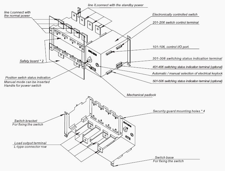
1, Electric lock: control the power of control circuit inside the switch. When the electric lock turned on, the switch can be remotely operated, otherwise the switch will be hand operation.
2, Operation handle: electric lock must be closed when using operation handle.
3, Mechanical padlock: Before you overhaul, you must turn off the electric lock, use the operating handle to force the switch to “0” position, pull the mechanical padlock and lock it.
4, Position indicator: indicate working status of the switch (I, 0, II).
5, The control voltage: AC220V.
6, The switch body: part in the front is line I, connect with the normal power. Part at the back is line II, connect with the standby power.


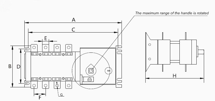
Model Specifications | A | B | C | D | E | F | G | H | |
SYK2-20-100A | 245 | 106 | 233 | 84 | 14 | 30 | 6 | 133 | |
SYK2-20-160A | JD | 303 | 135 | 280 | 110 | 20 | 36 | 9 | 195 |
YC | 80 | 190 | |||||||
SYK1-200-300A |
JD | 360 | 160 | 345 | 110 | 25 | 50 | 11 | 195 |
YC | 80 | ||||||||
SYK1-400-630A | 435 | 260 | 415 | 180 | 40 | 65 | 13 | 262 | |
SYK1-800-1000A | 635 | 326 | 610 | 220 | 63 | 120 | 9 | 321 | |
SYK1-1250A | 635 | 326 | 610 | 220 | 63 | 120 | 11 | 321 | |
SYK1-1600A | 635 | 360 | 610 | 220 | 80 | 120 | 13 | 321 | |
SYK1-2000-3200A | 635 | 400 | 475 | 350 | 80 | 120 | 13 | 505 | |
SYK series dual power automatic transfer switch is suitable for power system of insulation volt 750V, rated frequency 50HZ/60HZ, rated working volt 440V and below, rated current 20A~3200A. Widely used in high-rise buildings, telecom- munications, industrial and mining, shipping, power stations, hospitals, banks and other places need uninterrupted power supply.
SYK series ATS let the power supply system transfer between two power in emergency, the minimum conversion time is 0.3s to make sure the main load (emergency lighting, emergency staircase, fire-fighting system, etc) working continuously and reliably.

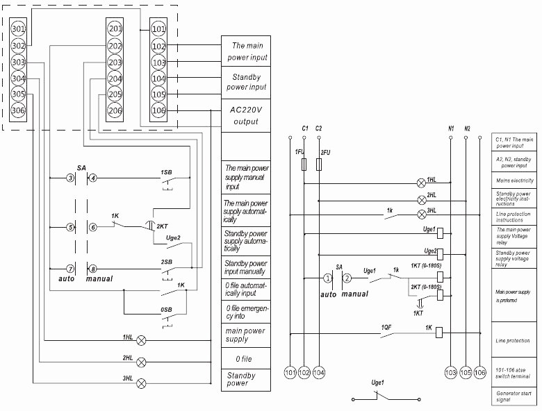
Note: 101-106 for switching power supply input and output terminals
201-206 for switch control terminals
301-306 for the switch status indication terminal
1 Qf primarily circuit (mains) protection switch alarm contacts
1 Kt for power on delay (0-180s), 2kt for power off delay (0-180s)
3.1.1 switch from left to right, I copper busbar connect with A, B, C, N of Commonly used power (in the front) and II connect with standby power (at the back).
3.1.2 control power is taken from C of commonly used power and N of standby Power
3.1.3. control power AC220V of line I connect to terminal 102-103, control power AC220V of line II connect to terminal 104-105, 102 is fire wire for commonly used power and 104 is fire wire for standby power.
3.1.4 terminal 101, 106, just as a light control power, of which 106 is fire wire. Note that 101, 106 can not connected to any other lines.
3.1.5 When the top (bottom) of line I inset wire, A, B, C, N at the bottom (top) use conection of copper busbar to output it. And line II use wires.
4.1 Common problems and solutions
Problems | Reasons | Solutions |
Power on, ATS does not work | 1. Whether the button pressed on the automatic position | Choose the automatic position |
2. Whether working power of the switch is connected | Access to the control power correctly | |
3. if connection mode of terminal 2 is correct | Access to signal control line correctly | |
4. The fuse is damaged | Replacing the fuse | |
Power on, circuit board burned | Check line 101-106 to make sure it is normal | Replace the circuit board |
Copyright © Guangxi Dingbo Generator Set Manufacturing Co., Ltd. All Rights Reserved | Sitemap
Update cookies preferences