Drive belts, checking and adjusting of Volvo Penta Engine
Inspection and adjustment should be carried out after running the engine when the belts are warm.
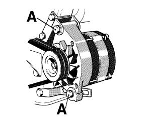
Undo the screws (A) before tensioning the generator belts. It should be possible to depress the belts 10 mm between the pulleys. Worn belts which work in pairs should be replaced at the same time.
The fan belts have an automatic belt tensioner and do not need adjusting. However, the condition of the belts must be checked. Replace if required.
Idling speed, adjustment
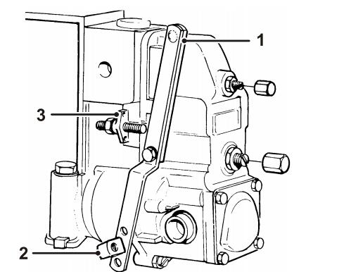
First check that the air filter is not clogged and that the throttle arm (1) on the fuel injection pump is against the idling speed stop (2) when the throttle mechanism is in idling position. Check also that the throttle arm presses against the max stop (3) when the throttle control is in the wide open throttle (WOT) position. Adjust the control if necessary.
Idling speed must only be checked and adjusted when the engine has reached normal operating temperature. For the correct idling speed, see chapter Engines.
WARNING!
Working with or approaching a running engine is a safety risk. Watch out for rotating components and hot surfaces.
RSV governor
1. Allow the engine to operate at low idling speed.
2. If necessary, adjust the engine speed by removing the domed nut (1), slackening off the locknut (2) and adjusting the engine speed with the screw (3).
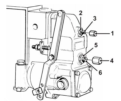
If the engine speed is uneven, the idle speed damping should be adjusted as follows:
1. Remove the domed nut (4) and slacken off the locknut (5). Carefully turn the damping screw (6) clockwise until the engine speed stabilises.
2. Check that the high idling speed has not changed. If it has changed, the damping screw (6) has been screwed in too far.
3. Lock the damping screw (6) and install the domed nut (4) when the adjustment is complete.
RQV, RQ governor
1. Allow the engine to operate at low idling speed.
2. If necessary, adjust the engine speed with the screw for low idling speed (1).
GAC governor
To adjust the idling speed on Generating set engines with GAC governor, refer to the separate documentation supplied with the GAC equipment.
Governor (Heinzmann)
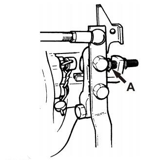
The governors of the T(A)D 420–731 GE series engines are mechanical variable-speed governors with centrifugal measuring element of M/s Heinzmann. All governor settings may only be conducted by trained specialists on a specifically laid out governor test bench.
Engine Fuel Filter Replacement
IMPORTANT
Cleanliness! No dirt or contaminants may enter the fuel injection system.
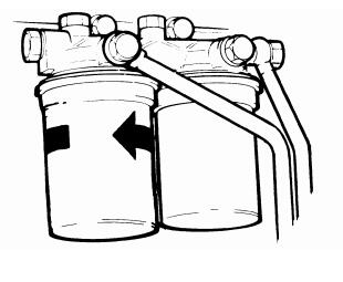
1. Remove the filters.
2. Moisten the new filter gasket with a little oil. Screw the filter into place by hand until the gasket touches. And then a further half turn but no more! Bleed fuel system.
NOTICE! Take the old filter to a suitable disposal point.
3. Start the engine and check for leaks.
Fuel system, bleeding
Is there “automatic stop in the event of too low oil pressure” with a Volvo Penta oil pressure switch? When the engine is of, this switch is closed (“NC” – Normally Closed) | |
Yes | No |
Disconnect the connector at the pressure switch. SB = Black BL - W = Blue-White | Is there “automatic stop in the event of too low oil pressure” with a non-Volvo Penta oil pressure switch that is open when the engine is off. (“NO” = Nomally Open) |
Is the engine equipped with a Volvo Penta instrument box? | Yes |
Short-circuit the connector for the oil pressure switch with a loop. | |
Yes | No |
Engines with a Volvo Penta instrument box | Engines with ignition switch
|
1. If there is a coolant level alarm – check the level. If the level is too low, the level alarm stops the engine. 2. Briefly press the “Starter button”. the instrumentation is now activeated and the charge lamp lights. If there is a coolant level alarm; Hold in the “Interlock button” for a proximatly 4 seconds. 3. Vent the fuel system according to the instruction on the next page. 4. Press the “Stop button”. 5. Reconnect the connector. 6. The engine is now operational. | 1. Turn the ignition switch to operating position/ignition. In Volvo Penta ignition switch position 1 (15+) 2. The solenoid valve is now activated for operation (not stop position). 3. Vent the fuel system according to the standard procedures (see the previous page). 4. The engine is now operational.
|
The fuel system must be vented after fuel filters have been replaced or after refilling the fuel tank after it has been run dry.
Venting engines with stop solenoid/fuel shut-off valve connected to supply voltage at stop:
Ensure that the engine is in operational mode. Open the bleed screw (1). Pump with hand pump (2) until fuel containing no air flows out. Close screw while fuel is flowing out.
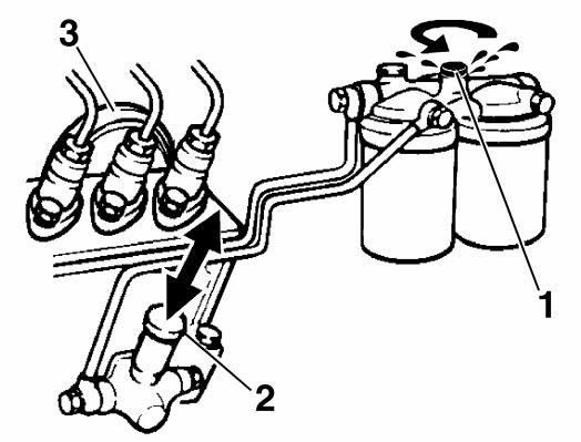
Then pump a further 15–20 times. Check for leaks.
NOTICE! For engines equipped with a fuel shut-off valve, the fuel injection pump often requires venting as well. This is done by slackening off the fuel injection pump pressure equaliser (3) (27 mm narrow U wrench). Pump with hand pump (2) until fuel containing no air flows out.
Engines 420–733:
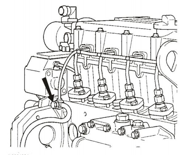
Open the air-venting plug in the overflow valve. (See fig.) Crank the engine on the starter motor or use the manual feedpump (optional equip.) until the fuel flow is free from air. Close the plug while the fuel is still flowing.
NOTICE! Do not loosen the injectors delivery pipes.
Coolant Filter, Change
NOTICE! Only engines with green coolant may be fitted with coolant filters.
Coolant filters are accessories. Their function is to filter the coolant and add anti-rust agent.
IMPORTANT
To prevent clogging resulting from anti-rust agent overdose, the filter may not be replaced at the same time as the coolant, but six months after the first coolant change, and then every 6 months.
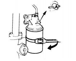
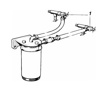
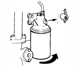
Close the cocks (1) or turn the cock to position "A" (16 liter). Remove the filter with a suitable filter remover. Moisten the gasket for the new filter and screw on the filter by hand. Turn an additional 1/2 turn once the gasket bottoms. Open the cocks (1) or turn the cock to position "B" (16 liter).
Electrical System
Fuses
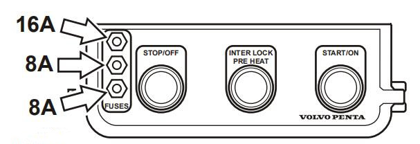
The engine has automatic fuses located in the junction box. The fuses break the current when there is an overload in the electrical system.
If the engine cannot be started or the instruments stop operating during operation, the fuse may have tripped. Reset the fuse by pressing on the button on the fuse.
IMPORTANT Always investigate the cause of an overload before resetting the fuse!
Battery
WARNING! Risk of fire and explosion. Never allow an open flame or electric sparks near the battery or batteries.
WARNING!
Battery electrolyte is a corrosive acid and should be handled with care. If you spill or splash electrolyte on any part of the body, immediately flush the exposed area with liberal amounts of water and seek medical attention as soon as possible.
WARNING!
Ventilate the engine compartment before working on batteries or battery connections.
IMPORTANT:
Batteries can be damaged if they are left discharged, and can also freeze and burst easier in cold weather. If the engine is not going to be used for a longer period of time, the batteries should be fully charged, trickle charged if possible.
Maintenance
It is important to always follow the battery manufacture’s recommendation and instruction when replacing and charging batteries. Depending on battery type the instructions for maintenance and charging may vary.
Modern batteries are normally maintenance free, but there are some actions that are recommended to increase the battery service life and avoid accidents:
• Keep the batteries clean and dry. Contamination and oxide on the batteries and battery poles can cause stray currents, voltage drop and discharge, especially in wet weather.
• Remove oxidation from the battery poles and terminals, using a brass brush.
• Tighten the terminals securely and grease them with terminal grease or petroleum jelly. Loose battery connections may cause damage to the engine’s electrical system.
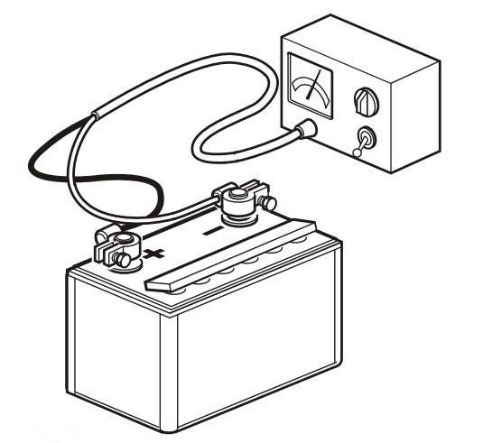
• Charge the battery regularly. A battery that is kept fully loaded has a maximum service life. The easiest way to check if a battery needs charging is to use a voltmeter.
Replacing Battery
IMPORTANT
Make sure that the new battery fulfills the specifications in Technical Data. Read the information supplied with the battery before you begin the installation.
IMPORTANT
Do not disconnect the batteries with the engine running as sensitive electrical components may be immediately damaged.
WARNING!
Never confuse the positive and negative poles on the batteries. Risk of arcing and explosion.
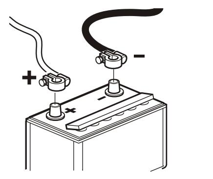
Disconnecting
1. Untighten the nut and remove the – cable (black).
2. Untighten the nut and remove the + cable (red).
3. Remove the battery.
Connecting
1. Place the new battery.
2. Connect the + cable (red) to the + pole on the battery and tighten the nut.
3. Connect the – cable (black) to the – pole on the battery and tighten the nut.
NOTICE! Hand the old battery to a re-cycling station.
Disengageable clutch
Lubrication
Use lithium based grease, Mobilux EP2, Statoil Uniway EP2N, Texaco Multifak EP2, Q8 Rembrandt EP2 for example.
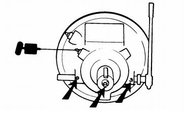
Main bearing and clutch mechanism
Lubricate inner support bearing (when a grease nipple is installed), main bearings, disengaging shaft and moving parts of clutch. Lubricate sparingly (20–30 g for main bearings).
Lubricate the inner control arms with a few drops of oil.
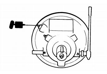
Disengagement bearing
Lubricate sparingly so that no grease is squeezed out. Use a grease recommended above.
Checking and adjusting
WARNING!
Stop the engine before doing any maintenance work.
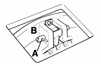
The clutch force at the end of the lever must be 34–41 kp (double clutch plates) or 36–45 kp (triple clutch plates) during engagement.
Adjustment: Remove the inspection cover. Disconnect catch (A) and turn the red adjuster (B) clockwise. Engage the catch. The clutch plates must not slip after engagement!
Air Compressor
Air Filter, Change
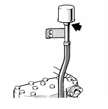
Slacken off hose clamp, remove the filter for disposal. Install a new filter and tighten the clamp.
If you interested in Volvo diesel generator, contact us to get the price.
Copyright © Guangxi Dingbo Power Equipment Manufacturing Co., Ltd. All Rights Reserved | Sitemap
Update cookies preferencesseokeywords:
test2