Volvo Diesel Engine Measurements
Checking the preheat relay
Tools:
9990014 Break-out cable
9998699 Break-out box
88890074 Multimeter
NOTICE! If any of the measurements shows an abnormal value, check the wiring to and from the engine control unit and the preheat relay.
Checking the wiring:
1 Cut the current with the main switch.
2 Remove connector B from the EMS2.
3 Connect the B connector to break-out cable 9990014 with break-out box 9998699.
4 Use multimeter 88890074 to do resistance measurement.
Measurement points | Nominal value |
25 (relay activation) - one of the preheat connectors | R ≈ 0 Ω |
57 (relay +) - one of the preheat connectors | R ≈ 0 Ω |
60 (relay +) - one of the preheat connectors | R ≈ 0 Ω |
Checking supply cable, fuel sensor
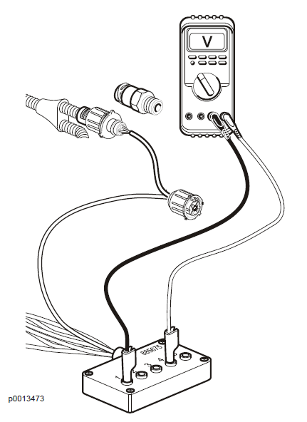
Tools:
885675 Break-out cable
88890074 Multimeter
1 NOTICE! Turn ignition off.
2 Disconnect the connector from the sensor.
3 Connect break-out cable 885675 to the cable harness connector to the engine control unit.
4 Use multimeter 88890074 for voltage measurement.
5 Turn ignition on.
Checking negative cable, fuel sensor
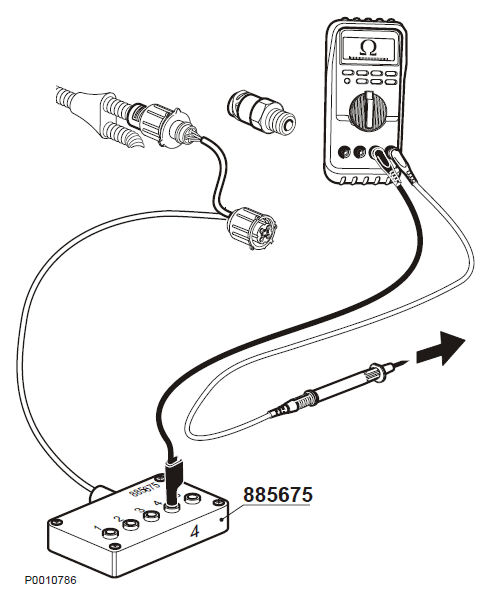
Tools:
885675 Break-out cable
88890074 Multimeter
1 NOTICE! Cut the current with the main switch.
2 Disconnect the connector from the sensor.
3 Connect break-out cable 885675 to the cable harness connector to the engine control unit.
4 Use multimeter 88890074 to do resistance measurement against the engine control unit.
Measurement points | Nominal value |
4 – Battery negative | R ≈ 0 Ω |
Checking signal cable, fuel sensor
Tools:
885675 Break-out cable
88890074 Multimeter
• NOTICE! Cut the current with the main switch.
• Disconnect the connector from the sensor
• Connect break-out cable 885675 to the cable harness connector to the engine control unit.
• Use multimeter 88890074 to do resistance measurement against the engine control unit.
Measurement points | Nominal value |
4–2 | R≈ 80-120 kΩ |
NOTICE! Measurement is done to eliminate short circuiting or breaks in the cable to the engine control unit.
Checking fuel pressure sensor
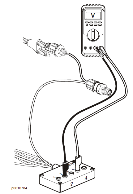
Tools:
885675 Break-out cable
88890074 Multimeter
1 NOTICE! Turn ignition off.
2 Disconnect the connector from the sensor.
3 Connect break-out cable 885675 between the sensor and the engine control unit.
4 Use multimeter 88890074 for voltage measurement.
5 Turn ignition on.
Measurement points | Nominal value |
4–2 | U ≈ 0,5 V* |
* At normal atmospheric pressure.
Checking supply cable, water in fuel switch
Tools:
88890074 Multimeter
1 NOTICE! Turn ignition off.
2 Disconnect the connector from the switch.
3 Use multimeter 88890074 to do a voltage measurement.
4 NOTICE! Turn ignition on.
Measurement points | Nominal value |
Yellow conductor – Black conductor | U ≈ Battery voltage x 0.8 |
Checking negative cable, water in fuel switch
Tools:
88890074 Multimeter
1 NOTICE! Cut the current with the main switch.
2 Disconnect the connector from the switch.
3 Use multimeter 88890074 to do resistance measurement against the engine control unit.
Measurement points | Nominal value |
Black conductor – Battery negative | R ≈ 0 Ω |
Checking water in fuel switch
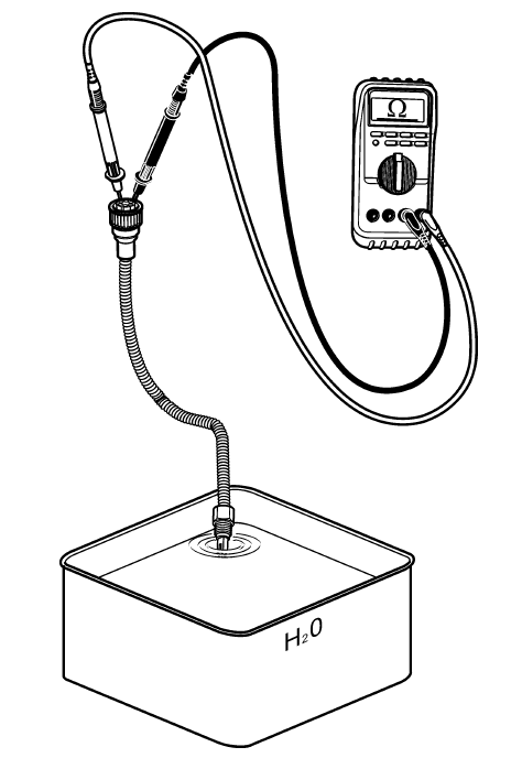
Tools:
9990014 Break-out cable
9998699 Break-out box
88890074 Multimeter
1 NOTICE! Cut the current with the main switch.
2 Disconnect the connector to the water in fuel switch.
3 Remove the water in fuel switch.
4 Use multimeter 88890074 to do a resistance measurement towards the switch.
Measurement points | Nominal value |
1-2, Switch immersed in water | R ≈ 0 Ω |
1-2, Switch immersed in fuel | R ≈ ∞ Ω |
Checking supply cable, oil pressure sensor
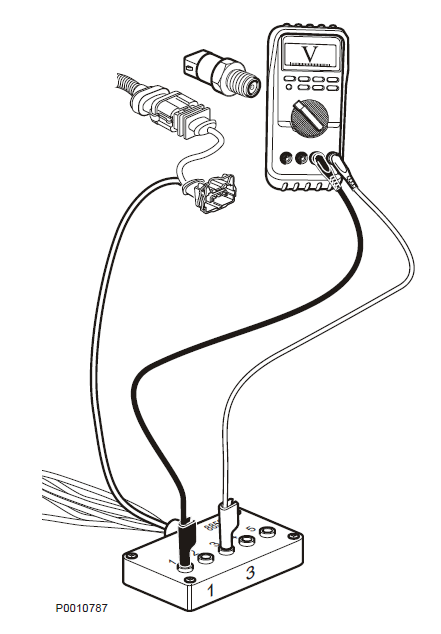
Tools:
885675 Break-out cable
88890074 Multimeter
NOTICE! If any of the measurements shows an abnormal value, check the wiring to and from the engine interface.
1 NOTICE! Turn ignition off.
2 Remove the connector from the sensor.
3 Connect break-out cable 885675 between the sensor and the engine control unit.
4 Use multimeter 88890074 for voltage measurement.
5 NOTICE! Turn ignition on.
Measurement points | Nominal value |
1–3 | U ≈ 5 V |
Checking negative cable, oil pressure sensor
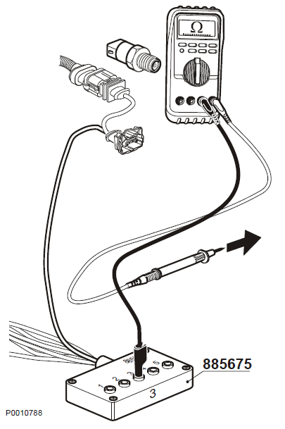
Tools:
885675 Break-out cable
88890074 Multimeter
1 NOTICE! Cut the current with the main switch.
2 Disconnect the connector from the sensor.
3 Connect break-out cable 885675 to the cable harness connector to the engine control unit.
4 Use multimeter 88890074 to do resistance measurement against the engine control unit.
Measurement points | Nominal value |
3 – Battery negative | R ≈ 0 Ω |
Checking signal cable, oil pressure sensor
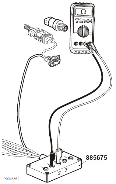
Tools:
885675 Break-out cable
88890074 Multimeter
1 NOTICE! Cut the current with the main switch.
2 Disconnect the connector from the sensor.
3 Connect break-out cable 885675 to the cable harness connector to the engine control unit.
4 Use multimeter 88890074 to do resistance measurement against the engine control unit.
Measurement points | Nominal value |
2–3 | R ≈ 80 – 120 kΩ |
NOTICE! Measurement is done to eliminate short circuiting or breaks in the cable to the engine control unit.
Checking oil pressure sensor
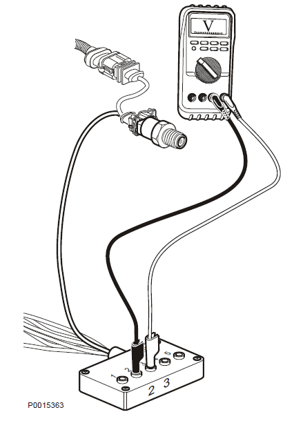
Tools:
885675 Break-out cable
88890074 Multimeter
1 NOTICE! Turn ignition off.
2 Disconnect the connector from the sensor.
3 Connect break-out cable 885675 between the sensor and the engine control unit.
4 Use multimeter 88890074 for voltage measurement.
5 Turn ignition on.
Measurement points | Nominal value |
2–3 | U ≈ 0.5 V* |
* At normal atmospheric pressure.
Checking signal cable, inlet manifold temperature sensor
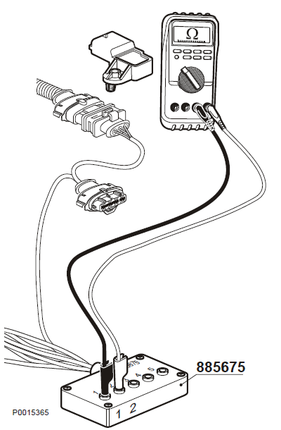
Tools:
885675 Break-out cable
88890074 Multimeter
NOTICE! If any of the measurements shows an abnormal value, check the wiring to and from the engine interface.
1 NOTICE! Turn ignition off.
2 Disconnect the connector from the sensor.
3 Connect break-out cable 885675 to the cable harness connector to the engine control unit.
4 Use multimeter 88890074 for voltage measurement.
5 Turn ignition on.
Measurement points | Nominal value |
1–2 | U ≈ 5 V |
Checking negative cable, inlet manifold pressure/temperature sensor
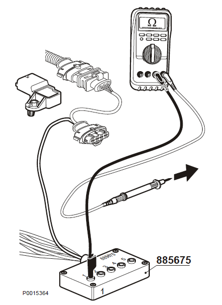
Tools:
885675 Break-out cable
88890074 Multimeter
1 NOTICE! Cut the current with the main switch.
2 Disconnect the connector from the sensor.
3 Connect break-out cable 885675 to the cable harness connector to the engine control unit.
4 Use multimeter 88890074 to do resistance measurement against the engine control unit.
Measurement points | Nominal value |
1 – Battery negative | R ≈ 0 Ω |
Checking sensor cable, inlet manifold temperature sensor
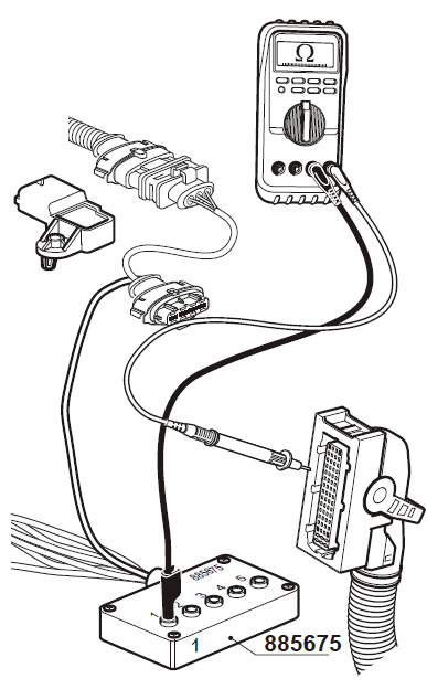
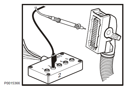
Tools:
885675 Break-out cable
88890074 Multimeter
Check for open circuit or short circuit:
1 NOTICE! Cut the current with the main switch.
2 Disconnect the connector from the sensor.
3 Connect break-out cable 885675 to the cable harness connector to the engine control unit.
4 Remove connector A from the engine control unit.
5 Use multimeter 88890074 to do a resistance measurement against the engine control unit connector A.
Measurement points | Nominal value |
2 (885675)– 47 (EMS 2, conn.A) | R ≈ 0 Ω |
2 (885675) – 11 (EMS 2, conn.A) | R ≈ ∞ Ω |
1 (885675) – 47 (EMS 2, conn.A) | R ≈ ∞ Ω |
1 (885675) – 11 (EMS 2, conn.A) | R ≈ 0 Ω |
NOTICE! Measurement is done to eliminate short circuiting or breaks in the cable to the engine control unit.
Checking inlet manifold temperature sensor
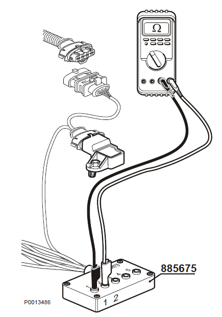
Tools:
885675 Break-out cable
88890074 Multimeter
1 NOTICE! Cut the current with the main switch.
2 Connect break-out cable (885675) to the sensor. Do not connect the other end of the adapter cable.
3 Use multimeter 88890074 to do resistance measurement.
Measurement points | Nominal value |
1–2 | R ≈ 9426 Ω +/- 470 Ω (vid -10° C) |
1–2 | R ≈ 5896 Ω +/- 332 Ω (vid 0° C) |
1–2 | R ≈ 2511 Ω +/- 109 Ω (vid 20° C) |
1–2 | R ≈ 1200 Ω +/- 47 Ω (vid 40° C) |
1–2 | R ≈ 612 Ω +/- 22 Ω (vid 60° C) |
1–2 | R ≈ 329 Ω +/- 11 Ω (vid 80° C) |
1–2 | R ≈ 186 Ω +/- 5 Ω (vid 100° C) |
1–2 | R ≈ 110 Ω |
Checking supply cable, inlet manifold pressure sensor
Tools:
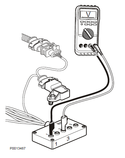
885675 Break-out cable
88890074 Multimeter
1 NOTICE! Turn ignition off.
2 Remove the connector from the sensor. Connect break-out cable 885675 between the sensor and engine control unit.
3 Use multimeter 88890074 for voltage measurement.
4 Turn ignition on.
Measurement points | Nominal value |
1–3 | U ≈ 5 V |
For More Volvo Engine workshop information, please visit
Fault Codes Information of Volvo Engine
Volvo Engine Control Unit Fault Codes
Copyright © Guangxi Dingbo Power Equipment Manufacturing Co., Ltd. All Rights Reserved | Sitemap
Update cookies preferencesseokeywords:
test2